
Instruction Manual
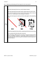

The Installer must avoid that a power supply positive or negative pole is
connected to the outputs.
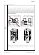
If a Receiving Unit's output is connected to a direct current inductive load
(by way of example: solenoid valves, relays), it is advisable to connect a
freewheeling diode in anti-parallel with the driven load, to reduce the eects
of demagnetizing currents.
A 12 or 24 V voltage must always be applied to the power supply input
of solid state outputs.
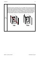
Common wire related to diodes of solid state outputs must be connected
with the common of all the Machine's freewheeling diodes. If that is not
possible, connect it to the Receiving Unit's power supply negative.
Pay special attention to the currents owing in the STOP and SAFETY
outputs: they shall not exceed the maximum permitted values (see chapter
"Technical Data" in "Part D" of the Instruction Manual) .
Wiring of STOP outputs is crucial to dene the safety level for the STOP
function (see the Installation Manual).
Wiring of SAFETY outputs is crucial to dene the safety level for the UMFS
protection function (see the Installation Manual).
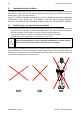
Single-insulation wiring cables shall be placed inside the Receiving Unit, in
such a way that they do not jeopardize the insulation amongst the circuits.
The Installer is in any case responsible for carrying out wiring in such a
way as to ensure the safety level required according to the risk analysis;
in particular, the connection of power supply's positive or negative pole to
the STOP outputs must be avoided.
AUTEC - Dynamic Series
Installation 35
LIUDYN002_eng-00