
User's Manual


AUTEC - Dynamic Series
Technical data 3
LICRXE00-01
The receiving unit is interfaced with the machine through the outputs and their wiring and/or
through a CAN network (of which it is a slave node).
The CAN communication of the CRX receiving unit can be enabled or disabled. The machine
manufacturer or who install the radio remote control on the machine determines whether the
CAN communication is enabled or disabled.
The STOP and SAFETY outputs are some of the receiving unit's outputs.
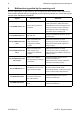
1.1 Safety functions of the CRX receiving unit
The SO1 and SO2 outputs may be either STOP (stop function) or SAFETY outputs (UMFS
function), according to the conguration of the receiving unit (see technical data sheet).
If they are congured as STOP outputs the UMFS safety function is not available.
If they are congured as SAFETY outputs both the UMFS and stop safety functions are
available.
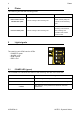
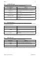
2 Technical data
Power supply ........................................................................................................ 8-30V
Antenna ............................................................................................. internal or dedicated
Rated current of SO_1 and SO_2 outputs ........................................................ 2A (30V )
Rated current of digital outputs ........................................................................ 2A (30V )
Protection of power supply (resettable fuse) ............................................................... 1.3A
Protection of outputs (fuse F1) ....................................................... 10A (32V , autofuse)
Housing material .......................................................................................... PA6 (20% fg)
Protection degree ....................................................................................... IP66 (NEMA 4)
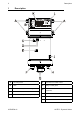
Dimensions ................................................................ 128x143x63mm (5.04x5.63x2.48In)
Weight ....................................................................................................... 0.65kg (1.43Lb)
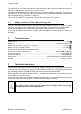
3 Technical data sheet
The technical data sheet contains the wiring diagram showing the connection between the
receiving unit and the machine. It also contains the transmitting unit conguration and shows
the matching between commands sent and machine functions/movements.
Each technical data sheet must be lled in, checked and signed by the installer, who is
responsible for a correct wiring.
A technical data sheet must always be kept toghether with this manual (always keep a copy
of the technical data sheet when it is used for administrative purposes).
The wiring of the receiving unit outputs must always reect the wiring
indicated in the technical data sheet.