
User's Manual
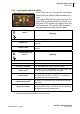
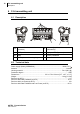
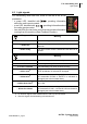
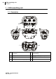
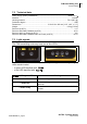
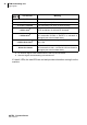
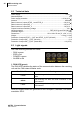
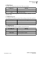
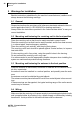
Table Of Contents

AUTEC - Dynamic Series
User manual
CRS receiving unit
Technical data
24
8.2 Technical data
Power supply ......................................................................................................... 8-30 V
Absorbed power............................................................................................................. 3 W
Power supply protection ............................................................................. 1.35 A (30 V )
Antenna ................................................................................................................ dedicated
Rated current of outputs STOP_1 and STOP_2 .............................................. 8 A (30 V )
Rated current of output SAF_1 ........................................................................ 8 A (30 V )
Rated current of output SAF_2 ........................................................................ 3 A (30 V )
Outputs' maximum switching voltage ....................................................................... 30 V
Housing material .............................................................. PBT (30% fg) and PA6 (30% fg)
Protection degree ..........................................................................................................IP65
Dimensions ................................................................ 153 x 148 x 55 mm [6’’ x 5.8’’ x 2.2’’]
Weight............................................................................................................0.5 kg [1.1 lbs]
Protection of outputs STOP_1_OUT and STOP_2_OUT (fail safe) ............................ 15 A
Protection of output SAF_1_OUT (fail safe) ................................................................ 15 A
Protection of output SAF_2_OUT (restorable) ................................................... 4 A (25°C)
8.3 Light signals
The CRS receiving unit has four LEDs:
- RUN is green
- ERR is red
- POWER is green
- ALARM is red
1. RUN LED (green)
The RUN LED indicates the status of the communication between the receiving
unit and the CAN network Master node.
RUN LED signals reflect the guidelines of the CANopen®, standard, CiA recom-
mendation 303-3.
The RUN LED ... Meaning
... is off
The receiving unit does not work as a CAN network
node.
...blinks
The receiving unit does not send commands in the
CAN network.
... is on
The receiving unit is working correctly as a node in the
CAN network.