
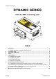
User's Manual

The receiving unit communicates with the machine thruough the output and the corresponding
wiring.
1.1 Safety functions of the ARX receiving unit
The SO1 and SO2 outputs may be either STOP (stop function) or SAFETY outputs (UMFS
function), according to the conguration of the receiving unit (see technical data sheet).
If thet are congured as STOP outputs the UMFS safety function is not available.
If they are congured as SAFETY outputs both the UMFS and stop safety functions are
available.
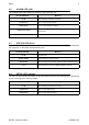
2 Technical data
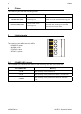
Power supply ........................................................................................................ 8-30V
Antenna .............................................................................................................. dedicated
Rated current of the SO1 and SO2 outputs ..................................................... 2A (30V )
Rated current of digital outputs ........................................................................ 2A (30V )
Rated current of analogue outputs (PWM) ....................................................... 2A (30V )
Rated current of analogue outputs (voltage) ............................................... 10mA (28V )
Protection of outputs (fuse F1) ....................................................... 10A (32V , autofuse)
Housing material .......................................................................................... PA6 (20% fg)
Protection degree ....................................................................................... IP66 (NEMA 4)
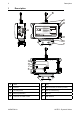
Dimensions ................................................................ 202x123x83mm (7.95x4.84x3.23In)
Weight ........................................................................................................... 1.2kg (2.7Lb)
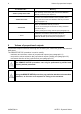
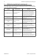
3 Technical data sheet
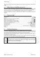
The technical data sheet contains the wiring diagram showing the connection between the
receiving unit and the machine. It also contains the transmitting unit conguration and shows
the matching between commands sent and machine functions/movements.
Each technical data sheet must be lled in, checked and signed by the installer, who is
responsible for a correct wiring.
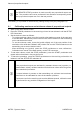
A copy of the technical data sheet must always be kept together with this manual (always
keep a copy of this data sheet for administrative purposes).
The wiring of the receiving unit outputs must always reect the wiring
indicated in the technical data sheet.
AUTEC - Dynamic Series
Technical data 3
LIARXE00-00