
Users Manual

6.5.4 Wiring
Wiringisunderstoodastheelectricalcableconnectionsthatcanbefound:
- inside the Receiving Unit,
- between the Receiving Unit and the Machine.
ALL ELECTRICAL CONNECTIONS MUST BE PERFORMED AND MADE IN
COMPLIANCE WITH THE NATIONAL ELECTRIC CODE AND ALL APPLICABLE
LAWS, REGULATIONS AND STANDARDS, EVEN LOCAL. IF INSTRUCTIONS
PROVIDED BY AUTEC ARE INCONSISTENT WITH SUCH APPLICABLE LAWS,
REGULATIONS OR STANDARDS, DO NOT INSTALL THE AUTEC RADIO
REMOTE CONTROL WITHOUT CONSULTATION WITH AUTEC. AUTEC IS
NOT RESPONSIBLE FOR AND SHALL NOT BE HELD LIABLE FOR ANY
MALFUNCTIONS OR ACCIDENTS THAT MAY OCCUR DUE TO ANY IMPROPER
INSTALLATION OR INCONSISTENCY BETWEEN ITS INSTRUCTIONS AND
SUCH LAWS, REGULATIONS OR STANDARDS.
FAILURE TO INSTALL THE AUTEC RADIO REMOTE CONTROL CORRECTLY
MAY RESULT IN PERSONAL INJURY OR DEATH, OR PROPERTY DAMAGE.
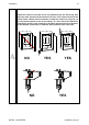
The power supply of the Receiving Unit must be connected using an omni
polar switch with a switch-contact gap of at least 3 mm, that allows power
supply disconnection during installation, wiring and/or maintenance
operations.
The Receiving Unit's power supply must be protected against short circuit
by means of an external device (by way of example: fuse, thermal magnetic
circuit breaker). Such device must be able to interrupt the maximum fault
current (including the short circuit current) allowed in the circuit.
Receiving units powered with AC and exposed to transient overvoltages
exceeding those of overvoltage category II, require additional protections
that must be provided outside of the Receiving units themselves.
If the Receiving Unit is powered with direct current, the power supply must
come:
- from a power supply unit with a safety isolating transformer, or
- from a 12/24V battery.
The Receiving Unit's relay outputs are designed to control high current
loads. Contacts of those outputs are protected by means of over-voltage
suppressors (varistors), to ensure the maximum lifetime of relays in most
applications.
32
LIUAIR003_eng-01
Installation
AUTEC - AIR SERIES