
User's Manual


1 Description
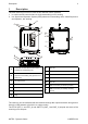
The ADD receiving unit can be used in two dierent control systems:
1. in a radio remote control where a single transmitting unit is working
2. in a Supervised Operator System (SOS) where two transmitting units, called Supervisor
and Operator, are working.
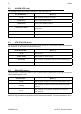
POWER SUPPLY...................................12-24V 300mA
........................................................max 8-30V 400mA
RADIO MODULE..............................................FSARTBEU2
FREQUENCY RANGE......................................863-870MHz
RF OUTPUT POWER.....................................
PROTECTION DEGREE...............................................IP65
<25mW ERP
TA1224-00 A0TARG01P0967
PU7355-00
Prima dell'accensione leggere il manuale d’uso.
Attenersi alle norme di sicurezza.
Togliere l’alimentazione in caso di apertura.
Non utilizzare idropulitrici ad alta pressione.
Before switching on please read the user manual.
Adhere to safety rules.
Disconnect power source before opening.
Do not use high pressure water cleaners.
Vor Inbetriebnahme die Gebrauchsanleitung lesen.
Sicherheitsnormen beachten.
Die Speisespannung muss ausgeschaltet
werden, falls der Empfänger geöffnet wird.
Kein Hochdruckreiniger verwenden.
Antes de encenderlo leer el manual.
Atenerse a las normas de seguridad.
Desconectar la alimentación antes de abrir.
Nunca usar hidrolimpiadoras de alta presión.
Avant de faire la mise en marche, lire le manuel
de l’utilisateur.
Respecter le consignes de sécurité.
Couper l’alimentation avant d’ouvrir le boîtier.
Ne pas utiliser nettoyeurs à jet d'eau sous pression.
SERIAL N. XXXXXX
MANIF. DATE XXXX
B
C
E
F
G
D
C
A
H
K
L
M
N
P
J
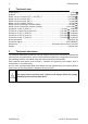
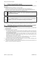
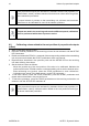
A
connector for the cable control of the
Supervisor transmitting unit
B
connector for the cable control of the
Operator transmitting unit (present in an
SOS only)
C mounting holes
D antenna
E LEDs
F TEACH pushbutton
G plug
H fuse F2
J fuse F1
K fuse F3
L fuse F4
M fuse F5
N DTK connector (for memory board)
P
BKK connector (for backup memory
board)
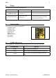
The receiving unit is interfaced with the machine through the outputs and their wiring and/or
through a CAN network (of which it is a slave node).
The STOP (STP_1 and STP_2) and SAFETY (SAF_1 and SAF_2) outputs are some of the
receiving unit's outputs.
AUTEC - Dynamic Series
Description 3
LIADDE00-00