
User's Manual
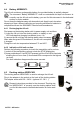
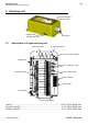
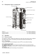
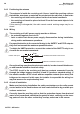
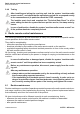
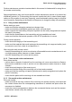
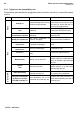
Table Of Contents

AUTEC - AIR series
36 Receiving unit
Description of type L receiving unit
5.2 Description of type L receiving unit
5.3 Operation
5.3.1 Electronic module
The electronic module contains the address key, where the radio remote control configura-
tion data are also stored. The receiving unit cannot work without this address key.
5.3.2 DIP switches
These two DIP SWITCHes shall always be set at OFF: do not modify this setting.
5.3.3 External signal lights
The ENABLE LED is off: the receiving and transmitting units are not communicating.
The ENABLE LED blinks: receiving unit G is ready to receive commands sent by the trans-
mitting unit
The POWER LED is on: the receiving unit is powered on.
Electronic module
DIP switches
Internal light signals
Command outputs
SAFETY outputs
STOP outputs
Fuses of STOP circuit
Power supply fuse
Fuses of SAFETY circuit
Fuse F1 ......................................................................................... 1.6 A F 250 V (5x20 mm)
Fuses F2 and F3 ............................................................................. 4 A T 250 V (5x20 mm)
Fuses F4 and F5 ............................................................................. 4 A T 250 V (5x20 mm)
Connector for power supply