
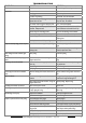
Technical data

Aussie Pumps Bertolini Pumps Service Guidelines - July 2008
15
AUSSIE BLASTER PRESSURE SETTING INSTRUCTIONS
Electric drive blasters
NOTE: These instructions are intended for the use of Authorised Aussie Eco-Clean service
centres only
1. Connect machine to mains pressure water supply, ensuring that water is passing freely through
the pump at the correct flow rate for specified pump by holding the gun trigger open.
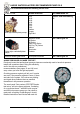
2. Check gun nozzle size with gauge to ensure correct nozzle size (see chart). Replace nozzle if
worn.
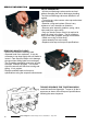
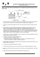
3. Ensure machine is set up correctly for testing with two gauges, as shown above. Pressure
gauge ‘A’ to be installed on top central valve cap. This gauge will measure the pump
pressure.Pressure gauge ‘B’ is to be installed at the pump outlet on the delivery hose. This
gauge will measure the in-line pressure when gun is shut off. This pressure must not exceed
20% increase on operating pump pressure. Example: 2000psi pump pressure on gauge ‘A’
with gun open: when gun is shut off gauge ‘B’ must not exceed 2400psi.
Measure amps on power supply cable to make sure amps are running at acceptable levels when
desired pump performance is obtained.
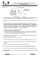
4. To obtain correct pressure at pre-determined rpm:
1. Remove grub screw in unloader lock ring;
2. Wind down unloader until required pressure is achieved. Check amp meter to ensure
electrical characteristics are within acceptable parameters.
5. Release trigger on gun to shut off water flow and read gauge ‘B’ to determine the increase in line
pressure (20% increase limit).
6. If test proves OK, repeat procedure for final check.
7. Unwind unloader by half a turn to ensure no pressure loss is indicated on gauge ‘A’ in pump.
8. Apply Loctite 243 Super Thread to grub screw in unloader lock ring and tighten with 1.5mm allen
key.
9. Apply paint seal to grub screw head and thread below unloader lock ring.
A
ussie Pumps Bertolini Pumps Service Guidelines – July 2011