
Install guide


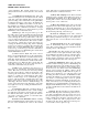


5-3. Target Set.
(See figure 5-2). The target set includes
a target, tribrach, and artificial illumination device. The
tribrach is the same that is used with the theodolite and
is provided with leveling screws and an optical plumb.
The target is black on white to provide a sharp aiming
point. It rotates on its base and has a level vial for use
in leveling, The target may be backlighted with the
illumination device, which is connected to the theodo-
lite battery box.
5-4. Setting Up the Theodolite and Target Set. The
theodolite and target set are mounted on tripods and
plumbed and leveled over the primary and azimuth
survey markers, respectively.
a. Setting Up the Tripod. The procedure for setting
up the trip
od is as follows:
(1) Upend the tripod and place the tripod head on
the toe of the shoe. Unbuckle the restraining
strap and secure the strap around the leg to
which it is attached.
(2) Loosen the leg clamp wing screws and extend
the tripod legs to the desired length. Tighten
the leg clamp wing screws.
(3) Turn the tripod to its upright position and test
the adjustment of each tripod leg by elevating
each leg, in turn, to a horizontal position and
(4)
(5)
(6)
(7)
ARMY TM 5-6675-308-34
MARINE CORPS TM 08837A-34/2
then releasing it, If the leg is properly ad-
justed, it should fall to about 45 degrees and
stop. If it does not, the tripod leg should be
adjusted by tightening or loosening the tripod
clamping nut. The test should be repeated
until successful.
Spread the legs and place the tripod over the
station to be occupied, with one leg approxi-
mately bisecting the angle(s) to be measured.
The head of the tripod should be set up at a
height which will place the telescope at a
convenient height for the operator.
Insert the plug-in sleeve of the plumb bob into
the instrument-fixture screw and extend the
plumb bob so that it will hang about an inch
above the station. Center the tripod approxi-
mately over the station.
Firmly embed the tripod legs, making sure
that the plumb bob is within one-half inch
(laterally) of being centered over the station
and that the tripod head is approximately level
when the legs are embedded.
Remove the tripod head cover and secure it to
the tripod leg.
b. Removing the Theodolite from its Case. To re-
move the theodolite from its case:
Figure 5-2. Tripod and Target Set
5-5