
Install guide


ARMY TM 5-6675-308-34
MARINE CORPS TM 08837A-34/2
d. PS Troubleshooting Subroutine No. 1 - Input
Power Short and Continuitv Checks. This subroutine
checks the circuits th
at carry the + 24v input power
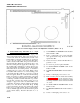
Figure 4-11. Power Supply Circuit Card Adjustment Locations (Sheet 2 of 2)
Set BATTERY and VEHICLE circuit breakers
CB1 and CB2 to OFF.
ahead of the main relay K1. The power supply runs on
+ 24V from either the vehicle battery at 3J4 or the
backup battery at 3J2. The normal mode of operation is
to use only the vehicle power through filter FL1,
vehicle circuit breaker CB2, and power diode CR2 to
the main relay K1. When the system draws more ower
than the normal path can supply (60 to 100 amps, or if
the normal path is intermpted, sequence monitor cir-
cuit card assembly A5 will turn on controlled rectifier
CR3. This allows the backup battery to maintain a
continuous flow of power to the system, When control-
led rectifier CR3 is turned on to connect backup power
to the main relay Kl, it will stay on as long as a current
flows through it, The flow of current from the backup
battery is sensed by a change in inductance of T1. This
is done to keep the battery charger off while CR3 is
conducting. Controlled rectifier CR3 will stop conduct-
ing and turn off when the vehicle voltage recovers
enough to support the total load. When CR3 is not
conducting, the battery charger will keep the backup
battery at + 28V, Power diode CR2 keeps backup
power from flowing out 3J4 to the vehicle if the vehicle
battery is low or if the vehicle starter is engaged. FL1
removes 40 kHz ripple that would otherwise be placed
on the vehicle battery. Perform subroutine no. 1 as
follows:
(1)
(2)
(3)
(4)
(5)
(6)
(7)
(8)
(9)
(lo)
(11)
If 0 to + 40V input power source still indi-
cates greater than 1 amp, the short remains:
replace filter FL1.
If short is removed, check from filter FL1-1 to
ground for + 5V.
If + 5V is not present, replace filter FL1.
Set PSTS INPUT POWER UUT circuit
breaker to OFF.
Set INPUT POWER PSTS circuit breaker to
OFF.
Set 0 to + 40V input power source to off.
Remove battery char er circuit card assembly
A7 (paragraph 4-19b(7)) far enough to discon-
nect connector A7P1. Leave transistors A706
and A7Q7 installed. Secure circuit card with
one screw.
Set PSTS INPUT POWER PSTS circuit
breaker to ON.
Set INPUT POWER UUT circuit breaker to
ON.
Set 0 to + 40V input power source to on.
4-120