
Install guide


ARMY TM 5-6675-308-34
MARINE CORPS TM 08837A-34/2
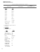
Table 4-19. PS Testing and Troubleshooting – Continued
Malfunction
Test procedure
Normal indication
indication/corrective action
Press POWER SUPPLY OFF switch, set
Multimeter indicates 100
FUNCTION switch to 115
LO,
press
to 121 VAC
POWER SUPPLY ON switch, and con-
nect multimeter to 115V
~90
and PWR
RTN test jacks
2ad.
Use oscilloscope to determine if
+17.0V remains on. If it does not,
replace +17V, converter-regulator
circuit card assembly A 1. If the +17
is present, replace power inverter
assembly A6
2ae.
2af.
2ag.
2ah.
2ai.
2aj.
2ak.
2a1.
2am.
2an.
2ao.
2ap.
2aq.
4-114
Disconnect multirneter from PSTS
Press POWER SUPPLY OFF switch, set
FUNCTION switch to PS AMB PWR
Set REFERENCE switch to AMB TEMP
+8V
Set DVM to DC volts. Press POWER
SUPPLY ON switch
Connect DVM test leads to POWER
SUPPLY AMB PWR HEAT and PWR
RTN test jacks
DVM indicates +16.0 to
+18.8V
Press POWER SUPPLY OFF switch and
set REFERENCE switch to AMB TEMP
V LAMP-5 VDC
Press POWER SUPPLY ON switch
Comect DVM test leads to POWER
DVM indicates +10.0 to
SUPPLY AMB PWR COOL and PWR RTN
+11.8V
test jack
Press POWER SUPPLY OFF switch
Set REFERENCE switch AMB TEMP
+8 VDC
Press POWER SUPPLY ON switch
Connect DVM test leads to POWER DVM indicates +25 to +29V
SUPPLY HTR 1 and PWR RTN test jacks
Connect DVM meter test leads to
DVM indicates +24 to +28V
POWER SUPPLY HTR 2 and PWR RTN
test jacks
If the voltage is out of tolerance or the
PS shuts off, replace +20V converter-
regulator circuit card assembly A2,
then sequence monitor circuit card
assembly AS, then K3
If the voltage is out of tolerance or the
PS shuts off, replace sequence moni-
tor circuit card assembly AS, then
+20V converter-regulator circuit card
assembly A2
Voltage out of tolerance: Replace
sequence monitor circuit card
assembly AS, then K2
Voltage out of tolerance: Replace K2