
Install guide


ARMY TM 5-6675-308-34
MARINE CORPS TM 08837A-34/2
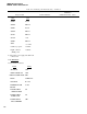
Table 4-19. PS Testing and Troubleshooting – Continued
Malfunction
Test procedure
Normal indication
indication/corrective action
Cable
W304P1
W304P2
W305P1
W305P2
W311P1
W311P2
W306P1
W306
Oscilloscope power
Digital voltmeter
(DVM) power
Unit
PS 3J4
PSTS J6
PS 3J2
PSTS J7
PSTS J5
+28V
PSTS J4
o to +40V
115VAC
115VAC
le. Disconnect power supply fan cable from
connector J6
2. PS TESTINGS
2a. Set switches as follows:
Switch Setting
SELF TEST
OFF
INPUT POWER UUT
OFF
INPUT POWER PSTS OFF
MODE
OVERLOAD
FUNCTION
PS +28V
REFERENCE AMB
O VDC
TEMP
POWER SUPPLY
ON
VEHICLE SENSE
POWER SUPPLY
ON
INTER LOCK
POWER SUPPLY
OFF
IMU OVERTEMP
4-110