
Install guide


ARMY TM 5-6675-308-34
MARINE CORPS TM 08837A-34/2
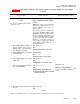
Table 4-14.1 IMU Testing, Alignment. and Troubleshooting Using Tape Reader, Part No. 877406-2 –
Continued
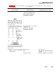
Malfunction
Test procedure
Normal indication
indication/corrective action
W203P1
SPU 20J3
W203P2
Tape Reader J1
W212
TTY
W212P1
SPU 20J12
W201P1
SPU 20J1
W201P2
115 VAC
TTY Power
115 VAC
W4P1
IMU 2J3
W4P2
PS 3J3
W2P1
IMU 2J1
W2P2
Computer 1J1
1y. Press SPU ON switch-indicator SPU ON switch-indicator lights
to on
1z. Set TTY printer MOTOR switch
to ON
1aa. Turn on + 28V power source
and set PS BATTERY and VE-
HICLE circuit breakers CB1
and CB2 to ON
1ab. Press PADS ON/OFF switch- PADS turns on
indicator to on
2. IMU TEST AND ALIGNMENT
NOTE
The IMU test program requires en-
try of data via the TTY. Data defini-
tions and formats are shown in table
4-16. Operator commands to check
test status and halt or initiate vari-
ous printouts are also given.
Use of the theodolite to measure
horizontal angles is described in
chapter 5.
2a. Press EXECUTE switch-indica-
EXECUTE switch-indicator lights
tor to on
TTY prints out:
PADS DIAGNOSTIC
ALIGN-
MENT PROGRAM or
PADS SOLID STATE DIAGNOS-
TIC ALIGNMENT PROGRAM
PROGRAM CHECKSUM XXXXXX
Change 7
4-90.5