
Install guide


ARMY TM 5-6675-308-34
MARINE
CORPS
TM 08837A-34/2
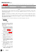
Table 4-14. IMU Testing, Alignment, and Troubleshooting — continued
Malfunction
Test procedure
Normal indication
indication/corrective action
Cable
Unit
W205P1 SPU 20J5
W205P2
W209P1
W209P2
W203P1
W203P2
W212
W212P1
W201P1
W201P2
TTY Power
W4P1
W4P2
Buffer Unit 21J1
SPU 20J9
Computer 1J3
SPU 20J3
Tape Reader J1
SPU 20J12
SPU 20J1
115 VAC
115 VAC
IMU 2J3
PS 3J3
W2P1
IMU 2J1
W2P2
Computer lJ1
ly. Press SPU ON switch-indicator
to on
1Z. Set TTY printer MOTOR switch
to ON
1aa.
lab.
Turn on + 28V power source
and set PS BATTERYand VE-
HICLE circuit breakers CB1
and CB2 to ON
Press PADS ON/OFF switch-
indicator to on
2. IMU TEST AND ALIGNMENT
NOTE
The IMU test program requires en-
try of data via the TTY. Data defini-
tions and formats are shown in table
4-16. Operator commands to check
test status and halt or initiate vari-
ous printouts are also given.
Use of the theodolite to measure
horizontal angles is described in
chapter 5.
2a. Press EXECUTE switch-indica-
tor to on
SPU ON switch-indicator lights
PADS turns on
EXECUTE switch-indicator lights
TTY prints out:
Change 1
4-85