
Install guide


ARMY TM 5-6675-308-34
MARINE CORPS TM 08837A-34/2
Table 4-14. IMU Testing, Alignment, and Troubleshooting – Continued
Malfunction
Test procedure
Normal indication
indication/corrective action
The fully loaded primary pallet weight exceeds
the two person lift criteria.
The weight may be reduced by removing the
power supply while the pallet is being moved.
NOTE
Leaving CDU connected in lieu of SPU,
enter SPH 800 to communicate with printer.
1v. If the system is not on the alignment sur-
face, disconnect the test equipment and
place the system on the alignment surface.
The porro prism should point 45 (±10)
degrees to any cardinal heading (Refer
to paragraphs 4-11c and 4-11d)
1w. Install the IMU in the primary pallet frame
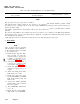
1x. Connect equipment as shown in figure 4-8
and the following checklist
Cable
Unit
W5P1
IMU 2J4
W5P2
PS 3J1
W5P3
IMU 2J5
W5P4
Computer Fan 5J1
W3P1
PS 3J5
W3P2
Computer PS 1J4
W6
Battery BOX
W6P1
PS 3J2
W211
+28V
W211
PS 3J4
W210P1
Computer 1J2
W210P2
Buffer Unit 21J2
4-84 Change 5