
Install guide


ARMY TM 5-6675-308-34
MARINE CORPS TM 08837A-34/2
4-11. IMU Testing, Alignment, Troubleshooting, and
Memory Matching Procedure.
a. General.
The IMU test and alignment procedure
is a lengthy (about 8 hours) test sequence which thor-
oughly checks out the IMU and recomputes many of
the software calibration parameters if no hardware
malfunctions are found. Most of the testing is per-
formed automatically under computer control. The
maintenance technician is required to reposition the
system and measure angles with a theodolite to cali-
brate the porro prism. Care must be taken to site the
system so it remains motionless during the test and is
properly oriented. The system must be provided with
survey coordinates so it can properly compute the
calibration constants. The computer memory used for
the test becomes matched to the IMU.
b. Test Equipment and Materials.
(1) PADS test set consisting of the signal proces-
sor unit (SPU), punched tape reader (tape reader), buffer
unit, interconnecting cables and auxiliary equipment.
(2) Teletypewriter. The 100-wpm motor-worm
gear must be installed prior to use. Refer to TM 11-
5815-200-12.
(3) PADS power supply, computer, pallet frame,
batter box, and CDU.
(4) +28V power source.
c.
Survey Requirements. The survey parameters for
a test site will be provided by an engineer survey unit.
The parameters required are:
(1) Latitude, in degrees, minutes, and seconds,
accurate to 5 arc-seconds.
(2) Elevation, in feet, accurate to 30 feet.
(3) Geodetic azimuth, in roils, accurate to 0.02
roil.
d. The azimuth orienting line must be located so
the maintenance technician’s theodolite is between 6
and 16 meters from the IMU porro prism and the
technician can autoreflect on the porro prism. The
porro prism will be oriented approximately 45 degrees
to the cardinal headings. (See figure 4-9.)
e. If only UTM coordinates, elevation in meters,
and/or grid azimuth are available, the system can be
used to translate them to the proper quantities as
follows:
(1)
(2)
4-78
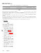
With the operational program installed in
memory, perform the test shown in table 3-1.
Use the correct values for casting, northing,
and elevation.
After elevation is entered, press: MON, ID,
3,0, ENT. Record the displayed latitude in
degrees, minutes, and seconds.
Change 5
(3) Press +2 twice to get to ID 32. Record the
elevation in feet.
(4) To obtain the geodetic (true) azimuth for a
grid azimuth:
(a) Press GAZ/TAZ. Record GAZ.
(h) Press GAZ/TAZ
again.
Display will show
TAZ C-E.
(c) Press ENT.
Record TAZ.
(d) Subtract GAZ from TAZ.
(e) Add the grid azimuth of the orienting line
to the difference to obtain the geodetic
azimuth.
Example:
TAZ
3902.61
GAZ
-3903.15
-0.54
Orienting line grid
+ 1245.23
azimuth
Geodetic (true)
1244.69
azimuth of
orienting line
f. Siting. The system must be on a level, stable
surface which will not move during the test. Surfaces
which are unacceptable include: maintenance van floor
or workbench, wooden floors, mud, snow, ice, loosely
packed sand, slippery clay, etc. Acceptable surfaces
include: concrete, dry packed earth, etc. Hot blacktop
may allow the system to sink slightly. Distribute the
load on blacktop and surfaces such as packed sand and
gravel by placing the system on the base of a transit
case or a four foot square of 3/4-inch-thick plywood or
similar material. The surface must be smooth enough so
the system does not
rock. A surface which can be
constructed to permit drainage of rainwater is shown in
figure 4-7. Pack the gravel to provide a firm base. Use
sand to fill the gravel voids and provide a smooth level
surface.
g. Normally, the alignment surface will be outside
a maintenance van. It must be close enough so the
cables from the test equipment will reach the system
while the test equipment remains in the van. The
alignment surface
must be situated so the porro prism
can be observed from the orienting line (refer to para-
graph 4-11c.).
h. Test Procedure. Perform the test in accordance
with table 4-14 or 4-14.1. Table 4-14 uses PADS test set
tape reader, part no.
877406-1 and table 4-14.1 uses
tape reader, part no,
877406-2. Table 4-15 is a sample
printout from an IMU test.
An interconnection diagram
is provided in figure 4-8.