
Install guide


ARMY TM 5-6675-308-34
MARINE CORPS TM 08837A-34/2
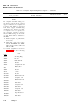
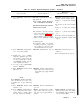
Table 4-6. Computer Diagnostic/Alignment Program - Continued
Malfunction
Test procedure
Normal indication
indication/corrective action
1k. Turn on + 28V power source
1l. Set PS BATTERY and VEHI-
CLE circuit breakers CB1 and
CB2 to ON
2. CPU TEST
NOTE
If any card assembly is replaced dur-
ing this test, repeat the test from
step 1h.
2a. Press PADS ON/OFF switch- PADS ON/OFF switch-indicator
indicator to on
lights. PARITY ERROR indicator
may light
IMU FAIL indicator lights. COMP
indicator may light
Comma in computer time totalizing
meter M1 oscillates
PADS ON/OFF switch-indicator
does not light: Computer power
supply malfunction. Remove and
troubleshoot in accordance with
table 4-20
Defective computer: Measure resis-
tance, with multimeter on 10
kilohm scale across computer
thermostatic switch S1. If less
than 500 ohms, disconnect lead
going to E23. If resistance is still
less than 500 ohms, replace ther-
mostatic switch S1. Refer to para-
graph 4-16c(3). If not, check for
wire harness short between E23
and E50. If shorted, repair or re-
place as required
If resistance is greater than 500
ohms, replace I/O discrete card
A9, then data buffer card A6
If resistance is greater than 2,000
ohms, check continuity between
E23, XA6-007, and XA9-003. Re-
pair if open
If comma does not oscillate, mea-
sure the voltage across the time
totalizing meter. If greater than
105 VAC, replace time totalizing
meter.
If less than 105 VAC,
check wiring
NOTE
The following step will be an aid in
determining memory unit type if un-
known.
4-50
Change 1