
Install guide


ARMY TM 5-6675-308-34
MARINE CORPS TM 08837A-34/2
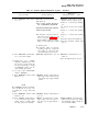
Table 4-6. Computer Diagnostic/Alignment Program — Continued
Malfunction
Test procedure
Normal indication
indication/corrective action
W212
TTY
W212P1 SPU 20J12
TTY Power 115 VAC
W201P1
SPU 20J1
W201P2
115 VAC
1f.
lg.
lh.
li.
lj.
Check that W4P1 is not con-
nected to IMU connector 2J3
Set tape
reader SPOOLING
switch to DISABLE
Press SPU ON switch-indicator
to on. Press to extinguish all
SPU lighted switch-indicators
except SPU ON and PADS OFF
Turn TTY printer MOTOR
switch to ON
Press and hold LAMP TEST
switch. Release after verifying
lamps light properly
SPU ON and PADS OFF switch-
indicators light. COMP FAIL in-
dicator may light. All lamps
pressed extinguish
All SPU lamps light except LAMP
If no lamps light, press and release
TEST and
ENTER and SELF TEST switch and press
FAILURE/ACTION indicator re-
LAMP TEST switch again
mains blank for at least 1.5 sec-
onds
FAILURE/ACTION indicator se-
If lamps are partially lighted, re-
quentially displays the following
place in
accordance with TM
within 15 seconds after pressing
5-6675-238-14
and/or TM
and
releasing
LAMP TEST
08839A-14/1
switch:
Indication
Blank
30
20
Blank
88
Blank
32
Blank
77
NOTE
For abnormal indication,
verify
equipment is connected as shown in
figure 4-3. Check connectors for
bent or broken pins. Troubleshoot
PADS test set in accordance with
TM 5-6675-238-14 and/or TM
08839A-14/1.
Change 1
4-49