
Install guide


ARMY TM 5-6675-308-34
MARINE CORPS TM 08837A-34/2
b. Procedure. Perform computer testing and trou-
4-7. The interconnections are shown in figure 4-3. Table
bleshooting in accordance with table 4-6 or 4-6.1 and
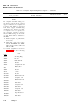
4-8 is a sample printout of the computer test.
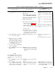
Table 4-6. Computer Diagnostic/Alignment Program
Malfunction
Test procedure
Normal indication
indication/corrective action
NOTE
This procedure uses tape reader, part no. 877406-1.
The test procedure column contains the test operation to be performed.
The Normal Indication column contains
the desired test set or teletype response to the test operation.
The malfunction indication(s) and corrective action(s)
are listed in the third column
All switches, switch-indicators, and indicators called out in the procedure are located on the SPU, unless otherwise
indicated.
To change a computer card assembly, perform the following in order given:
a. Press EXECUTE switch-indicator to off.
b. Press ON/OFF and ENTER switch-indicators.
c. Set PS BATTERY and VEHICLE circuit breakers CB1 and CB2 to off.
NOTE
Change 1 4-47
If memory unit is replaced, reloading with proper program may be necessary.
d. Change card assembly or memory unit. (Refer to paragraphs 3-15a or 3-15b.)
e. Set BATTERY and VEHICLE circuit breakers CB1 and CB2 to ON.
f. Press PADS/OFF switch-indicator to ON.
g. Repeat the test.
Check that tape reels are not deformed and that tape runs smoothly through tape reader head.
1. TEST SETUP
la. Mate computer to an opera-
tional power supply as necessary
NOTE
For memory, CDU, and IMU testing,
use the general support dedicated
computer. For computer testing, use
the suspected defective computer.
lb. Install memory unit in computer
as necessary