
Install guide


frame so that the same amount of frame (ap-
proximately 0.5-inch) is viable on both left and
right side of cutout.
(3) Using door frame as template, locate and cen-
terpunch the ten side die and bottom screw
holes. Remove the six 8-32 screws, washers,
and nuts; remove door frame.
(4) Drill the ten 3/16-inch screw holes.
o. Install Door Frame 880522-1 (4, figure 3-16,
sheet 6).
(1) Place door frame (4) in position and align the
screw holes with holes in rear panel.
(2) Install the ten side and bottom 8-32 X 3/4-
inch screws (5), washers (2), and nuts (l).
NOTE
The six top screws are installed when
door is installed.
p. Install Porro Prism Door 880521-1 (6, figure
3-16, sheet 6).
(1) Place porro prism door (6) against outer sur-
face of rear panel and align top screw holes in
door hinge with screw holes in rear panel.
(2)
Install 8-32 X 3/4-inch screws (5), washers (2),
and nuts (1) in each corner location.
(3) Attach the four spring retainers (3) to upper
and lower hin e halves usin four 8-32 X 3/4-
inch screws (5), washers (2), and nuts (l).
Engage springs (3) in spring retainers before
tightening the screws.
q. Install Latching Mechanism on Door (See figure
3-16, sheet 7).
(1)
(2)
(3)
(4)
(5)
(6)
(7)
(8)
Slide l/2-inch nylon washer (4) onto bolt of
door handle (3).
Insert door handle bolt through door (5) and
butt nylon washer against door panel.
Slide 1/2-inch nylon washer (4) onto door
handle bolt and butt against doubler on back
side of door panel.
Slide 1/2-inch washer (6) onto door handle
bolt and butt against nylon washer.
Slide spring washer (7) onto door handle bolt
and butt against washer (hollow side against
washer).
Install 1/2-20 jamnut (8) on door handle bolt
and butt against spring washer. Tighten
jamnut only until handle operates smoothly.
Install plunger ball (2) in pawl (9) and tighten.
Place pawl (9) onto door handle bolt and butt
against jamnut.
ARMY TM 5-6675-308-34
MARINE CORPS TM 08837A-34/2
(9) Install 1/2-inch locknut (1) on door handle
bolt.
(10) Close door and make sure that it closes se-
curely, Adjust plunger ball (2) as required.
r. Install Air Pipe 880546 (Transition Joint) and
Flex Hose 880520-59 (See figure 3-16, sheets
8
and
9).
(1)
(2)
(3)
(4)
(5)
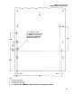
Mark and drill 1/4-inch diameter holes in both
sides of the air intake hood as shown in figure
3-16, sheet 8.
Slide two Tinnerman nuts (2) over the hole
drilled in air intake hood. Make sure the
smooth side faces outside the hood.
Slide the air pipe (1) over the air intake hood
and secure with two sheet-metal screws (2,
figure 3-16, sheet 9).
Slide the two clamps (4) onto the flex hose (5)
and sli the hose over the heater flange and air
pipe (3) base.
Route the flex hose (5) to clear installed equip-
ment and tighten clamps.
s. CDU Mounting Bracket Installation. Drill holes
for CDU mounting bracket on dashboard as
follows:
(1) Remove passenger grab bar from dashboard.
(2) Using sheet 8 of figure 3-16 as a guide, mark
mounting hole locations on dashboard.
(3) Center punch and drill two 5/16-inch diame-
ter holes through dashboard. If vehicle does
not have holes for a grab bar, drill the right
grab bar hole also.
(4) Secure mounting
hardware (three 10-32
screws, lockwashers, washers, and nuts) to the
dashboard for later use by the PADS crew.
t. Install Rear Panel in Vehicle. Install rear panel
as follows:
(1) Place rear panel in position in vehicle.
(2) Install the five 1/4-20 X l/2-inch cap screws
and washers securing angle bracket to vehicle
rain gutter. Tighten the screws.
(3) Install three 5/16-24 X 3/4-inch screws and
washers on each side and secure side mounting
plates to vehicle body.
(4) Install two 5/16-24 X 3/4-inch screws and
washers and secure bottom plate to vehicle
body.
u. Removal of Rear Panel After Installation of
Winterization Kit.
3-59