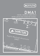
DMA1 D I GI TAL M E S S AGE AN N OU N CER INS TA LLAT I ON AN D OP E RAT I ON M AN UAL REMO T CONTR E OL SD/MM MEMOR C Y VOLUM ON PLAY Digita 2-24 DC IN E l Mess age A nnoun DMA1 cer LOGIC INP 1 2 3 UTS 4 5 6 7 8 PRE PRE IN OUT L R L R SPK OUT L R E
I M P O RTA N T SAF E TY INF ORMATION 1. Save the carton and packing material even if the equipment has arrived in good condition. Should you ever need to ship the unit, use only the original factory packing. 2. Read all documentation before operating your equipment. Retain all documentation for future reference. 3. Follow all instructions printed on unit chassis for proper operation. 4. Do not spill water or other liquids into or on the unit, or operate the unit while standing in liquid. 5.
INTRODUCTION AND CONTENTS 1. INTRODUCTION 1.1 1.2 1.3 1.4 1.5 1.6 1.7 4 6.1 6.2 6.3 Introduction What is MP3? Encoder Decoder Player Wave Audio compression in various formats 2. INSTALLATION 2.1 2.2 4. Contents of the DMA1 kit Notices 6 Command description Connection description Power supply Logic inputs IN/OUT 8 - Vlink input/output Serial RS485 connection Line level audio input Line level audio output Amplified audio output 5.1 5.2 5.3 5.4 7.1 7.2 8.
INTRODUCTION 1.1 Introduction 1.4 Decoder The Australian Monitor Installation Series DMA-1 digital message announcer is a compact yet highly featured digital playback device. Utilizing an SD card digital storage format the DMA1 delivers high quality stereo audio in an MP3 format. Messages can be played or triggered using the on-board controls, via remote switches, contact closure or via RS485 serial control.
I N S TA L L AT I O N 2.1 Contents of the DMA1 kit 2.2 Notices 1x DMA1 device 1. The DMA1 has been designed to work only with the following mains power supply adaptors: 12-15VAC, 12-24VDC. 2. The device must be serviced only by qualified staff. 3. In order to prevent the risk of fire or shock do not put objects inside the device through openings 4. Disconnect the device from power before cleaning. Clean the device using a soft, dry cloth.
DESCRIPTION AND CONNECTIONS 3.1 Command description 1 Connector for external connection of memory and command buttons 2 Flash memory slot for Secure Digital or MultiMedia Card 3 Command keys: = (brief pressure) previous MP3 file / (prolonged pressure) reduce output volume = STOP = PLAY = (brief pressure) next MP3 file / (prolonged pressure) increase output volume 4 Red LED: 5 Green LED: lit = device is on lit = MP3 file playing; blinking = DMA1 in pause/STOP.
DESCRIPTION AND CONNECTIONS 3.2 Connection description 6 VAC/DC Power input 12-15VAC or 12-24VDC 6 +12VDC Auxiliary + 12Vdc voltage, available for input activation or external feed sensors. MAX. 100mA 7 GND Ground for input activation using external contacts; auxiliary ground voltage 7 IN1 Multi-function input for activating 1.mp3 file or 1.
DESCRIPTION AND CONNECTIONS 3.3 Power supply 3.6 Serial RS485 connection The DMA1 may operate with the following main power adaptors: 1215VAC, 12-24VDC. It is recommended to use the mains adaptor supplied with the device. The red POWER LED lights up when power is present. The DMA1 can be connected to an RS485 bus that can be controlled by a Crestron control system, or any other RS485 enabled control system.
C O N F I G U R AT I O N F I L E 4.1 What is the configuration file? 4.3 How it is managed by the DMA1 The DMA1 is a very versatile device which can be adapted to the needs of the application in which it is used. Different applications may require adjustment of volume, tone, loudness, communication parameters and timing. The configuration file stored in the main directory of the flash memory, together with the audio files, makes it possible to programme the various parameters of the DMA1.
C O N F I G U R AT I O N F I L E 4.
C O N F I G U R AT I O N F I L E LBAS (BASS TONE CONTROL) VALUE 0 1 2 3 4 5 6 7 8 9 10 11 12 13 14 15 16 17 18 19 20 LEVEL -12 dB -10 dB -8 dB -7 dB -6 dB -5 dB -4 dB -3 dB -2 dB -1 dB 0 dB +1 dB +2 dB +3 dB +4 dB +5 dB +6 dB +7 dB +8 dB +10 dB +12 dB MOMD (MODE OUTPUT MUTING DISABLE) MOMD 1 = Muting Deactivated (Internal Power Amplifier Always Active) 0 = Muting Active (Internal Power Amplifier Is Only Active During The Playing Of The Mp3 Files) 4.
C O N F I G U R AT I O N F I L E 4.
C O N F I G U R AT I O N F I L E 4.9 Input management parameters The playing of MP3 files takes place by activating the logic inputs. The activation modes are set through the IMOD, TPCM MICP and MIRS parameters inserted in the configuration file.
C O N F I G U R AT I O N F I L E 4.10 Infrared movement sensor management parameters IMPORTANT: the following parameters are enabled exclusively for the IN1 input.
S C H E D U L E D O P E R AT I O N NOTE: It is very important to start a new line of text for each event, and to separate the hours from the minutes using the (:) character. 5.1 Introduction to timed operation When the flash memory card is inserted, the DMA1 will analyse its “ contents and – depending on the files which are present – will automatically set the mode of operation. In the presence of the PALIN.
S C H E D U L E D O P E R AT I O N IMPORTANT! When using the line level audio inputs, check the settings of the LLIN, LLI2 and MOMD parameters inserted in the configuration file (par. 4.6). Programming limits: Max. programming time permitted 1 hour (cyclic) Max. quantity of time events 60 events Max. quantity of MP3s per time event 8 MP3 files Max. quantity of MP3s per palimpsest 500 MP3 files 5.
P L AY L I S T O P E R AT I O N 6.1 Introduction to playlist mode operation When the flash memory is inserted, the DMA1 analyses its content to define its mode of operation based upon the files present: 1. 2. File: PLAYLIST.TXT plays audio files in sequence according to the list present in the file File: 1.M3U, 2.M3U, 3.M3U, 4.M3U, 5.M3U, 6.M3U, 7.M3U plays audio files in sequence according to the list present, activated by logic input IN1 = 1.m3u IN5 = 5.m3u IN2 = 2.m3u IN6 = 6.m3u IN3 = 3.m3u IN7 = 7.
C O N F I G U R AT I O N F I L E 6.4 MPLL=10: Stop & Play Priority playlist Operating mode: • Upon activation of a logic input, the first MP3 in the playlist is played. At the end of the MP3 file the DMA1 goes in standby, awaiting further logic input activation.
P L AY L I S T O P E R AT I O N 6.5 MPLL=11: Priority playlist Operating mode: • Upon activation of a logic input, the MP3 files in the playlist are played in sequence. At the end of the playlist the DMA1 goes in standby, awaiting further logic input activation.
O P E R AT I O N W I T H L O G I C I N P U T S 7.1 Logic input operating mode 7.2 Binary input command codes The DMA1 can also play individual MP3 audio files with direct selection from eight logic inputs (par. 3.4). The DMA1 enters this working mode if there are no PALIN.TXT and PLAYLIST.TXT files present. Activating the logic inputs in binary combination allows the playing of up to 255 messages, named according to the audio files as shown in the following table.
O P E R AT I O N W I T H L O G I C I N P U T S 1 2 3 INPUT 4 5 6 7 8 = File.mp3 RELEVANT FILES / MESSAGES O 1 O 1 1 O O O = 26.mp3 1 1 O 1 1 O O O = 27.mp3 O O 1 1 1 O O O = 28.mp3 1 O 1 1 1 O O O = 29.mp3 O 1 1 1 1 O O O = 30.mp3 1 1 1 1 1 O O O = 31.mp3 O O O O O 1 O O = 32.mp3 1 O O O O 1 O O = 33.mp3 O 1 O O O 1 O O = 34.mp3 1 1 O O O 1 O O = 35.mp3 O O 1 O O 1 O O = 36.
O P E R AT I O N W I T H L O G I C I N P U T S 1 2 3 INPUT 4 5 6 7 8 = File.mp3 RELEVANT FILES / MESSAGES O O O 1 O O 1 O = 72.mp3 1 O O 1 O O 1 O = 73.mp3 O 1 O 1 O O 1 O = 74.mp3 1 1 O 1 O O 1 O = 75.mp3 O O 1 1 O O 1 O = 76.mp3 1 O 1 1 O O 1 O = 77.mp3 O 1 1 1 O O 1 O = 78.mp3 1 1 1 1 O O 1 O = 79.mp3 O O O O 1 O 1 O = 80.mp3 1 O O O 1 O 1 O = 81.mp3 O 1 O O 1 O 1 O = 82.
O P E R AT I O N W I T H L O G I C I N P U T S 1 2 3 INPUT 4 5 6 7 8 = RELEVANT FILES / MESSAGES O 1 1 O 1 1 1 O = 118.mp3 1 1 1 O 1 1 1 O = 119.mp3 O O O 1 1 1 1 O = 120.mp3 1 O O 1 1 1 1 O = 121.mp3 O 1 O 1 1 1 1 O = 122.mp3 File.mp3 1 1 O 1 1 1 1 O = 123.mp3 O O 1 1 1 1 1 O = 124.mp3 1 O 1 1 1 1 1 O = 125.mp3 O 1 1 1 1 1 1 O = 126.mp3 1 1 1 1 1 1 1 O = 127.mp3 O O O O O O O 1 = 128.
O P E R AT I O N W I T H L O G I C I N P U T S 1 2 3 INPUT 4 5 6 7 8 = RELEVANT FILES / MESSAGES O O 1 O O 1 O 1 = 164.mp3 1 O 1 O O 1 O 1 = 165.mp3 O 1 1 O O 1 O 1 = 166.mp3 File.mp3 1 1 1 O O 1 O 1 = 167.mp3 O O O 1 O 1 O 1 = 168.mp3 1 O O 1 O 1 O 1 = 169.mp3 O 1 O 1 O 1 O 1 = 170.mp3 1 1 O 1 O 1 O 1 = 171.mp3 O O 1 1 O 1 O 1 = 172.mp3 1 O 1 1 O 1 O 1 = 173.mp3 O 1 1 1 O 1 O 1 = 174.
O P E R AT I O N W I T H L O G I C I N P U T S 1 2 3 INPUT 4 5 6 7 8 = RELEVANT FILES / MESSAGES O 1 O O 1 O 1 1 = 210.mp3 1 1 O O 1 O 1 1 = 211.mp3 O O 1 O 1 O 1 1 = 212.mp3 1 O 1 O 1 O 1 1 = 213.mp3 O 1 1 O 1 O 1 1 = 214.mp3 File.mp3 1 1 1 O 1 O 1 1 = 215.mp3 O O O 1 1 O 1 1 = 216.mp3 1 O O 1 1 O 1 1 = 217.mp3 O 1 O 1 1 O 1 1 = 218.mp3 1 1 O 1 1 O 1 1 = 219.mp3 O O 1 1 1 O 1 1 = 220.
SPECIAL FUNCTIONS 8.1 Connection of two DMA1s Connecting two DMA1s in cascade via the Vlink connection and the audio inputs/outputs (see figure), can recreate the typical operating mode of a commercial radio station. DMA1 with playlist REMOTE CONTROL One DMA1 must be programmed to run in playlist mode, playing the musical items (PLAYLISTS.TXT), the other DMA1 is programmed to run according to a schedule (PALIN.TXT) playing the commercials/spot announcements.
SPECIAL FUNCTIONS 8.2 Amplifier Bridging (40W) The DMA1 has the capability of bridging the outputs of the stereo power amplifier to create a 40W bridge-mono configuration - to power a single 8ohm loudspeaker of greater power capacity. To enable this operational mode, in addition to wiring the speaker in a bridged configuration, it is necessary to set the following parameters in the config.
S E R I A L R S 4 8 5 C O M U N I C AT I O N 9.1 RS485 communication IMPORTANT! The DMA1 can be connected to a Crestron control system or similar via RS485 serial connection.
S E R I A L R S 4 8 5 C O M U N I C AT I O N Position P1 and P2 jumpers: IN5 and IN6 inputs with logic operation. (Default Position P1 and P2 jumpers: IN5 and IN 6 inputs enabled to the operation as RS485 serial port.
S E R I A L R S 4 8 5 C O M U N I C AT I O N 9.2 Serial port communication parameters (config.txt) IMPORTANT! notes for the control system The parameters of the RS485 serial port (length of the packets, parity, speed, etc.) are set in the configuration file config.txt. The DMA1 is ready for serial communication instructions under the following conditions: These parameters must be compatible with the external control system to which DMA1 is connected.
S E R I A L R S 4 8 5 C O M U N I C AT I O N Reply wait time (CMDR) 9.6 Basic format of dedicated protocols This is the delay time before the transmission of a reply message, required by some control systems to switch between the state of transmission and the state of reception. The reply waiting time determines the minimum delay before the DMA1 sends data in reply to the message received from the control system.
S E R I A L R S 4 8 5 C O M U N I C AT I O N IMPORTANT! The introduction of CheckSum at the end of the block of data and characters of CR + LF is defined in the configuration file config.txt (par. 9.2). 9.8 Control codes The control codes are characters (they belong to the first 32 ASCII characters and cannot be printed out) which define the type of information contained in the packet following them. The control codes used are those which appear on the following table.
S E R I A L R S 4 8 5 C O M U N I C AT I O N 9.11 CheckSum (CHK) CheckSum ensures that packets are complete and not corrupted during transmission by any noise or interference induced on the RS485 bus. The CheckSum is calculated summing the hexadecimal values of the ASCII characters contained in the data packet (excluding the control code).
S E R I A L R S 4 8 5 C O M U N I C AT I O N 9.
S E R I A L R S 4 8 5 C O M U N I C AT I O N 9.13 Basic protocol with CheckSum Reading the data of the DMA1 from the control system Transmission sequence * E A C C N D M H Q D D K Control System DMA1 S A C T D M X D D D AT A E C T H X K * Sending a command to the DMA1 from the Control System Transmission sequence E A C N D M Q D D The DATA block is inserted only if provided for by command used C D AT A H K Control System DMA1 * 1. 2.
S E R I A L R S 4 8 5 C O M U N I C AT I O N 9.
S E R I A L R S 4 8 5 C O M U N I C AT I O N 9.15 Basic protocol with CheckSum, CR and LF Reading the data of the DMA1 from the control system Transmission sequence * E A C N D M Q D D C L R F Control System DMA1 S A C T D M X D D E T D AT A X C L R F * Sending a command to the DMA1 from the Control System Transmission sequence * E A C N D M Q D D D AT A C L R F The DATA block is inserted only if provided for by command used Control System DMA1 * 1. 2.
S E R I A L R S 4 8 5 C O M U N I C AT I O N 9.16 List of commands and operating fields This table provides a list, with the relevant comments, of all the commands managed by the DMA1.
S E R I A L R S 4 8 5 C O M U N I C AT I O N 9.17 Error codes The following table lists all the error codes which the DMA1 delivers together with the NAK packet if problems are found. CODE DESCRIPTION 10H Failure to convert command code (CMD). It could contain characters which are outside the representation of a hexadecimal value. The permitted values are: ‘a’ .. ‘f’ ‘A’ …. ‘F’ ‘0’….’9’ 11H Failure to convert the value contained in ‘DATA’ into a number.
S P E C I F I C AT I O N S POWER SUPPLY 12-15VAC or 12-24VDC CONSUMPTION IN STANDBY 1W PROTECTION internal fuse, 4A delayed CAPACITY OF EXTRACTABLE MEMORY SD/MMC from 32MB to 1GB INPUT ABSORPTION 5 mA FORMATS ACCEPTED MPEG1 layer 3 (file MP3 from 64 to 160 Kbps) FREQUENCY RESPONSE 20 ~ 20.000 Hz (±3dB) SIGNAL/NOISE RATIO > 90dB HARMONIC DISTORTION < 0.1% OUTPUT POWER AUDIO CONTROLS 20+20W ( 24V / 4 Ω ) THD= 0.
NOTES PA G E 4 1
PA G E 4 2
NOTES PA G E 4 3
AUSTRALIA AND NEW ZEALAND w w w. a u s t r a l i a n m o n i t o r. c o m . a u SYDNEY MELBOURNE BRISBANE ADELAIDE PERTH AUCKLAND (NSW & ACT SALES) (VIC & TAS SALES) (QLD SALES) (SA & NT SALES) (WA SALES) (NZ SALES) 149 Beaconsfield Street Silverwater NSW 2128 Private Bag 149 Silverwater NSW 1811 Phone: (02) 9647 1411 Fax: (02) 9648 3698 Email: nsw@audiotelex.com.