
Specifications
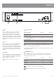

PAGE 6 AMC
+
SERIES INSTALLATION AND OPERATION MANUAL
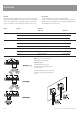
INSTALLATION
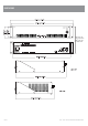
Mounting
When rack mounting, it is advisable to allow 1 rack space above and below the
amplifi er. When multiple amplifi ers are mounted in a rack, exhaust fans should
be used on the rack. Airfl ow for cooling the AMC
+
120P is by convection from
bottom to top. Airfl ow for cooling the AMC
+
250P is by fan from front to side.
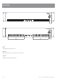
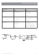
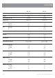
Direct Output
The output terminal strip accepts wire sizes from 16-22AWG
(1.5mm2 – 0.35mm2) or spade lugs. The following table should be used as a
guideline for cable sizes. Regulations in your area may require different gauged
wire and should be checked before using.
Output Distance Wire Size
AMC
+
120P AMC
+
250P
100V Up to 50m AWG24(0.2mm
2
) AWG22(0.35mm
2
)
50m–200m AWG18(0.75mm
2
) AWG16(1.5mm
2
)
Over 200m AWG16(1.5mm
2
) AWG13(2.5mm
2
)
70V Up to 50m AWG22(0.35mm
2
) AWG18(0.75mm
2
)
50m–200m AWG16(1.5mm
2
) AWG13(2.5mm
2
)
Over 200m AWG13(2.5mm
2
) AWG10(6.0mm
2
)
4 ohm Up to 10m AWG18(0.75mm
2
) AWG18(0.75mm
2
)
10m–30m AWG13(2.5mm
2
) AWG13(2.5mm
2
)
Over 30m Not Recommended Not Recommended
Note: Only connect one output – either
Distributed Line or Low Impedance.
Input Connections
For wiring balanced in, pin 2 is hot.
Balanced input wiring (shielded pair cable)
is recommended.
When wiring unbalanced in. pin2 is hot and pin
1 and pin 3 should be shorted together to the
shield.