ACM120XL 120w Mixer Amplifier Operating Manual
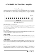
ACM120XL, 120 Watt Mixer Amplifier Product Description The ACM120XL is a 120 watt mixer amplifier designed for commercial installations. It features 8 microphone/line input channels and can be used for either low impedance (4 or 8 ohm) or 70v/100v line speaker systems. A host of unique features including multiple levels of muting, a VOX relay output and VCA master level control make the ACM120XL a very flexible amplifier.
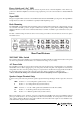
Power Switch and “On” LED The black rocker switch on the right hand side of the front panel is used to switch the amplifier on and off. The ‘up’ position is on. When the amplifier is connected to an appropriate AC power source and is switched on, the blue LED will illuminate. Signal LED The green “Signal” LED located next to the On LED indicates that the ACM120XL is passing audio. The signal LED is a simple method to trouble-shoot installations especially in multi-amplifier projects.
VOX Relay Output The terminal strip to the immediate right of the AC inlet features a relay output. This relay is activated when signal is present on any of the priority inputs. This would normally be inputs 1, 2 and 3 however some or all of these channels can be removed from the priority bus via internal links (see “Muting” further on in this manual).
Line Output A 3 pin male XLR socket is provided to allow for connection to additional power amplifiers. The line level signal is the mixer output of the ACM120XL allowing this “mixed” signal to be split to other amplifiers. This is most commonly used when more power (than the 120 watts of the ACM120XL) is required. In this situation, a standard microphone lead is used to connect the line output of the ACM120XL to the line input of a power amplifier.
Muting for any of the first three inputs can be disabled. The muting circuit of input 1 can be disabled by moving the jumper labelled JP1 (located on the front mixer PCB behind input 1 and 2’s level controls). Simply move the jumper towards the back of the chassis to disable muting from input 1. To disable muting from input 2, simply move jumper JP2 towards the back of the chassis. To disable muting from input 3, simply move jumper JP3 towards the back of the chassis.
Important Safety Information 1. Save the carton and packing material even if the equipment has arrived in good condition. Should you ever need to ship the unit, use only the original factory packing. 2. Read all documentation before operating your equipment. Retain all documentation for future reference. 13. Do not block fan intake or exhaust ports.
Engineered by Audio Telex Communications Pty Ltd, Sydney, Australia A.B.N. 78 001 345 482 Inc in NSW www.audiotelex.com.au Export Sales & Corporate Head Office Private Bag 149, Silverwater NSW 1811 149 Beaconsfield Street, Silverwater NSW 2128 Australia Ph: 61-2- 9647 1411 Fax: 61-2-9748 2537 E-mail: ho@audiotelex.com.au Sydney (NSW & ACT Sales) Private Bag 149, Silverwater NSW 1811 149 Beaconsfield Street, Silverwater NSW 2128 Ph: (02) 9647 1411 Fax: (02) 9648 3698 E-mail: nsw@audiotelex.com.