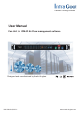
Cabinet Cooling Solution User Manual Fan Unit & ICM-02 Air Flow management software Designed and manufactured by Austin Hughes UM-ICM-02-Q215V1 www.austin-hughes.
Legal Information First English printing, October 2002 Information in this document has been carefully checked for accuracy; however, no guarantee is given to the correctness of the contents. The information in this document is subject to change without notice. We are not liable for any injury or loss that results from the use of this equipment. Safety Instructions Please read all of these instructions carefully before you use the device. Save this manual for future reference.
Unpacking The equipment comes with the standard parts shown on the package contents. Check and make sure they are included and in good condition. If anything is missing, or damage, contact the supplier immediately. UM-ICM-02-Q215V1 www.austin-hughes.
Content Part I. Installation P.1 < 1.1 > 1U Fan Tray < 1.2 > 33U Door Mount Fan Panel Part II. Hardware P.6 < 2.1 > Key Features < 2.2 > Fan Kit Specification < 2.3 > Master IP Fan Unit Model & Specification MRF-1.3 ( 1U Fan Tray with 3 fans ) MRF-1.6 ( 1U Fan Tray with 6 fans ) MRF-1.9 ( 1U Fan Tray with 9 fans ) MRF-33.9 ( 33U Door Mount Fan Panel with 9 fans ) Specification Table < 2.4 > Remote Fan Unit Model & Specification RF-1.3 ( 1U Fan Tray with 3 fans ) RF-1.
Part III. Software P.23 < 3.1 > Key Features < 3.2 > Master IP Configuration < 3.3 > Hardware Requirements of the Management PC < 3.4 > Supported OS Platform & Language < 3.5 > Software Download < 3.6 > First Time Start-up Setting < 3.7 > Change Port no. of Web Server Part IV. System Setup & Remote Access P.29 < 4.1 > System Setup < 4.2 > Remote Access Part V. Software Usage & Operation P.36 Part VI. Events / Log / Report P.39 Part VII. SNMP P.42 Part VIII. FAQ P.44 Part IX.
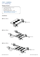
< Part I > Installation < 1.1 > 1U Fan Tray Package Content - 1U rackmount fan tray x 1 pc - Temp. sensor x 1 pc - 6 ft power cord x 1 pc - Rear mounting bracket x 1 pair * Bracket for MRF-1.6 / 9 & RF-1.6 / 9 only * M6 screws for fixing are not included Installation MRF-1.3 / RF-1.3 M6 screws MRF-1.6 / RF-1.6 Rear mounting brackets M6 screws MRF-1.9 / RF-1.9 M6 screws Rear mounting brackets UM-ICM-02-Q215V1 P.1 www.austin-hughes.
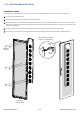
< 1.2 > 33U Door Mount Fan Panel MRF-33.9 & RF-33.9 Door mount Fan Panel are typically installed on the outside of a cabinet’s rear perforated door to improve extraction of heat from high density cabinet. The unit can be attached to most 42U or taller cabinets. If aisle is relatively narrow for exterior mounting, the unit may be installed on the inside of the perforated door.
< 1.2 > 33U Door Mount Fan Panel Caution - Power off the fans if the door is to be opened for maintenence or service of items within the cabinet. The fans have finger guards but care must be excerised when working around spinning fans. Keep hair, fingers and other small objects away from the spinning blades. UM-ICM-02-Q215V1 P.3 www.austin-hughes.
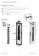
< 1.2 > 33U Door Mount Fan Panel Installation steps The weight of the unit is less than 5.5 kg, so in most cases, holes in perforated cabinet doors can be used to mount the unit. 1 Lift the unit to the desired position. 2 Place attached 6 screws then through the door and tighten them.
< 1.2 > 33U Door Mount Fan Panel Hanging bracket installation 1 Assemble & adjust the hanging bracket with M4*6mm screw & nut, to fit the thickness of the door. 2 Install the hanging bracket kit on the rear side of the fan panel with M4*10mm screw. 3 Hang the unit on the door. 4 Place attached 4 screws then through the door and tighten them. 5 Follow steps 3 - 5 on P.4 .
< Part II > Hardware < 2.1 > Key Features Daisy Chain Position Master IP Fan Unit Remote Fan Unit 1st Level 2nd - 16th Level 3 / 6 / 9 fans 3 / 6 / 9 fans 6 / 9 fans 6 / 9 fans IP Port Daisy Chain Port - LINK Daisy Chain Port - OUT Temp. Port Temp. Sensor Control Panel : - Individual Fan On / Off - Alarm Temp. Setting - Unit CFM ( fan speed ) Setting - Temperature LED - Fan Status LED - CFM Status LED 1U Fan Tray Door Mount Fan Panel UM-ICM-02-Q215V1 P.6 www.austin-hughes.
< 2.2 > Fan Kit Specification Fan Specification Air Delivery : Rate Speed : Rated Voltage : Rated Current : Noise Level : Dimension : Bearing System : UM-ICM-02-Q215V1 P.7 108 CFM 3000 rpm, +/-10% 12V DC 350 mA 41 dB 120 x 120 x 25 mm Dual ball bearing www.austin-hughes.
< 2.3 > Master IP Fan Unit Model Model : MRF-1.3 1U Fan Tray with 3 fans 2 - Unit CFM Status LED - Unit CFM Setting 1 - Individual fan status - Individual fan On / Off buttons 4 - DIP switch for daisy chain level setting 3 - Buttons for Alarm Temp. Setting - Temp. LED display 5 6 7 TEMP IP OUT 5 - Temp. port bundled w/ a temp.
< 2.3 > Master IP Fan Unit Model Model : MRF-1.6 1U Fan Tray with 6 fans 2 - Unit CFM Status LED - Unit CFM Setting 1 4 - DIP switch for daisy chain level setting 3 - Individual fan status - Individual fan On / Off buttons - Buttons for Alarm Temp. Setting - Temp. LED display 5 6 7 TEMP IP OUT 5 - Temp. port bundled w/ a temp.
< 2.3 > Master IP Fan Unit Model Model : MRF-1.9 1U Fan Tray with 9 fans 2 - Unit CFM Status LED - Unit CFM Setting 1 4 - DIP switch for daisy chain level setting 3 - Individual fan status - Individual fan On / Off buttons - Buttons for Alarm Temp. Setting - Temp. LED display 5 6 7 TEMP IP OUT 5 - Temp. port bundled w/ a temp.
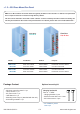
< 2.3 > Master IP Fan Unit Model Model : MRF-33.9 33U Door Mount Fan Panel with 9 fans Front View Side View Top View 195 mm 42.9 mm 195 mm 4 TEMP 5 IP 6 OUT 7 1466 mm UM-ICM-02-Q215V1 P.11 4 - DIP switch for daisy chain level setting 5 - Temp. port bundled w/ a temp.
< 2.3 > Master IP Fan Unit Specification Table Master IP Fan Model MRF-1.3 / 1.6 / 1.9 MRF-33.9 No. of Fan 3 / 6 / 9 9 Mounting 1U Door mount CFM Level Normal / High / Max.
< 2.4 > Remote Fan Unit Model Model : RF-1.3 1U Fan Tray with 3 fans 2 - Unit CFM Status LED - Unit CFM Setting 1 - Individual fan status - Individual fan On / Off buttons 4 - DIP switch for daisy chain level setting 3 - Buttons for Alarm Temp. Setting - Temp. LED display 5 6 7 TEMP LINK OUT 5 - Temp. port bundled w/ a temp.
< 2.4 > Remote Fan Unit Model Model : RF-1.6 1U Fan Tray with 6 fans 2 - Unit CFM Status LED - Unit CFM Setting 1 4 - DIP switch for daisy chain level setting 3 - Individual fan status - Individual fan On / Off buttons - Buttons for Alarm Temp. Setting - Temp. LED display 5 6 7 TEMP LINK OUT 5 - Temp. port bundled w/ a temp.
< 2.4 > Remote Fan Unit Model Model : RF-1.9 1U Fan Tray with 9 fans 2 - Unit CFM Status LED - Unit CFM Setting 1 4 - DIP switch for daisy chain level setting 3 - Individual fan status - Individual fan On / Off buttons - Buttons for Alarm Temp. Setting - Temp. LED display 5 6 7 TEMP LINK OUT 5 - Temp. port bundled w/ a temp.
< 2.4 > Remote Fan Unit Model Model : RF-33.9 33U Door Mount Fan Panel with 9 fans Front View Side View 195 mm 42.9 mm 195 mm 4 TEMP 5 LINK 6 OUT 7 4 - DIP switch for daisy chain level setting 5 - Temp. port bundled w/ a temp. sensor 6 LIN K port for connecting - Daisy chain LINK to the out port of the last level fan unit 7 - Daisy chain OUT OU T port for connecting to the link port of the next level fan unit 1466 mm UM-ICM-02-Q215V1 P.
< 2.4 > Remote Fan Unit Specification Table Remote Fan Model RF-1.3 / 1.6 / 1.9 RF-33.9 No. of Fan 3 / 6 / 9 9 Mounting 1U Door mount CFM Level Normal / High / Max.
< 2.5 > Daisy Chain Connection Steps : ■ ■ ■ ■ Only Master IP fan unit built-in IP remote access module. Master IP fan unit MUST be set on the 1st daisy chain level according to the table below. For the 2nd - 16th levels ( remote fan unit models ), please make the level setting according to the table below. For the cabling connection, please refer to the next page. ON OFF Daisy chain level setting Using the dip switch no.
< 2.5 > Daisy Chain Connection Remarks : ■ ■ ■ ■ ■ Each Master IP group supports 16 daisy chain levels. The 1st level fan unit must be one of the Master IP fan unit models. 1 x Master IP fan unit allows access to 16 levels. For IP fan unit access, simply connect 1 x Master IP fan unit. The 2nd - 16th level fan unit must be one of the Remote fan unit models. 2nd level Remote fan unit model 1st level Master IP fan unit model IP OUT 3rd level Remote fan unit model OUT LINK Cat5 / 6 cable max.
< 2.6 > Audio Temperature Alarm Setting Using the dip switch no. 7 to setup each FAN unit audio alarm as below : Enable Disable Dip switch 7 On Off If enable the audio alarm, the buzzer will sound when the outside temperature is over the preset alarm temperature. < 2.7 > Temperature Sensor TEMP Bundled Temp. Sensor Part no. : IG - T01 - 2M - Plug & Play - External sensor with 2M cord - Low profile design with magnetic base for easy affixing to the rack cabinet Optional 4M cord for Temp.
< 2.7 > Temperature Sensor Temp. Sensor Part no. Temperature Sensitivity IG-T01 Range 0 to 80°C ( 32 to 176°F ) Accuracy ±1°C ( ±2°F) Resolution 0.1°C ( 0.2°F ) Response Time Power Requirement Housing 5 to 30 sec Voltage 12VDC, powered by sensor port Current Consumption 20mA Power consumption 0.
< 2.8 > Alarm Temperature Setting How to set alarm temperature : ■ Hold ■ Press for 5 seconds. button to set the alaram temperature. The alarm temp. can be set either by these buttons or software. How to set temp. unit ( Celsius or Fahrenheit ) : ■ Hold ■ Press for 5 seconds. button to set the temp. unit. The above steps are only for local LED temp. display. Users need to set the temp. unit ( °C or °F ) in the software GUI separately. < 2.
< Part III > Software < 3.1 > Key Features InfraCool Manager ICM-02 is a FREE Air Flow management software to remote & monitor up to 30 Master IP Groups ( max. 16 fan unit levels in each Master IP Group), total 480 fan units. 5 concurrent user access are bundled for achieving the demand of multi-user / multi-tasking in nowadays’ time sharing data center operation.
< 3.2 > Master IP Configuration Please take the following steps to configure the Master IP fan unit : 1. Prepare a notebook computer to download the IP setup utilities from the link : http://www.austin-hughes.com/support/utilities/infracool/IPSetupUtilities.msi 2. Double click the IPSetupUtilities.msi and follow the instruction to complete the installation. 3. Go to each Master IP fan unit with the notebook computer & a piece of CAT. 5 / 6 cable to set up the configuration by IP setup utilities as below.
< 3.3 > Hardware Requirement of the Management PC Please prepare a management PC with the hardware requirements as below for InfraCool Manager - ICM-02 Recommended hardware requirements : - Processor: Dual Core 2GHz or above - Memory: 2GB RAM - Available Disk Space: 500GB - Drive: DVD ROM drive - Display: 1440 x 900 or higher resolution monitor - The default service port of web server is 80. - A dedicated PC to run InfraCool Manager - ICM-02 is recommended.
< 3.5 > Software Download InfraCool Manager, ICM-02, is a AIR FLOW management software to monitor the temperature change by providing a centralized and remote management platform, and total reporting with detailed logs & event occurrences. InfraCool Manager ICM-02 can support max. 5 concurrent login users and manage multi- Master IP group max. 30, hence the concurrent login users can access & remote FAN units max. 480 ( 30 Master IP groups x 16 level fan units ).
< 3.6 > First Time Start-up Setting Step 1. Double click the InfraCool Manager - ICM-02 and follow the instruction to complete start-up setting. ICM-02 InfraCool Manager Step 2. Click “ Next “ in “ InfraCool Manager start-up setting “ box Step 3. Input the fields of the following window & Click “ Install “ If the port of web server is not 80, please input the appropriate no. here and follow the instruction in “ Change port no. of web server“ on next page to make the change effective.
< 3.7 > Change Port no. of Web Server Change port no. of web server. If users want to use another port no. instead of 80, please take the following steps after InfraCool Manager ICM-02 “ First time start-up setting “ is completed. Step 1. Go to the path of web server being installed. ( Default: C:\AppServ\Apache2.2\conf\ ) Step 2. Open “ httpd.conf “ & change “ Listen 80 “ to “ Listen xx “ where xx means the port users want to use save the change Step 3. Restart Apache services.
Part IV. System Setup & Remote Access < 4.1 > System setup Users can follow below step 1 - 3 to access the management PC and InfraCool Manager ICM-02 Step 1. Open Internet Explorer ( I.E. ), version 8.0 or above Step 2. Enter the URL of management PC into the address bar ( If fail to access, please ask MIS to check if the port for web server is enable. Default port : 80 ) e.g. http://192.168.0.1/ICM-02/ Step 3. Enter “ User name “ . Default is “ admin “ Enter “ Password “ .
< 4.1 > System setup In < User > page, administrator can create 4 more operators. Step 1. Tick “ Operator 1: “ Step 2. Input “ User name “ & “ User login password “ Step 3. Input user login password in “ Confirm password “ again Step 4. Repeat Step 1 to 3 for other operators if necessary Step 5. Click “ Apply “ to finish the user setup UM-ICM-02-Q215V1 P.30 www.austin-hughes.
< 4.1 > System setup In < Setup > page, administrator can activate max. 30 Master IP groups & set the group command password Step 1. “ Activate “ Master IP group 01 Step 2. Input “ IP address “ & “ password “ of the Master IP group 01 Step 3. “ Enable “ Command password Step 4. Input “ New command password ”. Default is “ 00000000 “ Step 5. Input new command password in “ Confirm new password “ again. Step 6. Click “ Apply “ to finish the Master IP group setup Step 7.
< 4.1 > System setup In < Alarm > , administrator can configure the alarm email server & max. 5 email recipients to receive alarm notifications from the software Step 1. “ Enable “ alarm email Step 2. Input “ SMTP server “ , “ SMTP port “ Step 3. Input sender email account in “ User email “ Step 4. “ Enable “ or “ Disable “ the “ SMTP authentication “ Step 5. Input “ User name “ and “ Password “ Step 6. Select the “ SMTP secure “ ( None / SSL / TLS ) Step 7. Input the “ Alarm interval “ Step 8.
< 4.1 > System setup In < General > , administrator can change the “ Refresh rate “ , “ Scan rate “ & “ Temperature unit “ across all Master IP groups In < Backup > , administrator can “ Enable “ or “ Disable “ the daily data backup. When “ Enable “, the backup path can be changed UM-ICM-02-Q215V1 P.33 www.austin-hughes.
< 4.1 > System setup < Sys log > provides last 2000 events in < User >, < Setup >, < Alarm >, < General > & < Backup > . UM-ICM-02-Q215V1 P.34 www.austin-hughes.
< 4.2 > Remote Access After administrator completes < System Setup >, up to 4 additional users can access the management PC remotely. User can follow the steps below to access management PC & InfraCool Manager ICM-02 Step 1. Add the port of web server in the firewall settings of the management PC.
Part V. Software Usage & Operation < Status > provides - < Search > function to search new installed fan units in each Master IP group. - Scan function to monitor the fan units’ status of each Master IP group ONE by ONE UM-ICM-02-Q215V1 P.36 www.austin-hughes.
Part V. Software Usage & Operation In < Details >, - Change “ Rack “ and “ Position ” of Fan unit - Switch ON / OFF fan unit - Change fan unit CFM - Switch ON / OFF individual fan - Click “ Apply ” to finish the above settings UM-ICM-02-Q215V1 P.37 www.austin-hughes.
Part V. Software Usage & Operation In < Temp setting >, - “ Activate ” or “ Deactivate ” Temp sensor - Change “ Location ”, “Alarm Setting ” & “ R. alert setting “ of Temp sensor - “ Enable “ or “ Disable “ auto CFM control - Click “ Apply ” to finish the above settings The default Temp setting is Deactivate . - When install Temp sensor, please tick - DON’T Activate . Otherwise, no readings display. activate Temp sensor if no sensor installed. UM-ICM-02-Q215V1 P.38 www.austin-hughes.
Part VI. Events / Log / Report < Event > provides past 2000 events about FAN unit’s configuration & connection in a certain Master IP Group. < FAN unit log > provides past 2000 FAN unit log records about a certain FAN unit by the user’s selection. The software will generate a FAN unit log record in every 10 mins. UM-ICM-02-Q215V1 P.39 www.austin-hughes.
Part VI. Events / Log / Report < FAN log > provides past 2000 FAN log records about an individual fan of specific fan unit by the user’s selection. The software will generate a FAN log record in every 10 mins. UM-ICM-02-Q215V1 P.40 www.austin-hughes.
Part VI. Events / Log / Report < Report > provides monthly report for export to csv format. Fan unit log , Fan log & Event log which can be Please follow the steps below to export the log category you want : Step 1. Select the category, period & target. Step 2. Click “ Apply ” & Click “ OK “ from the pop up window Step 3. Right click the file name below & select Save target as to download the log file. Step 4.
Part VII. SNMP SNMP Management The Master IP fan unit can manage the connected remote fans ( up to 16 remote fans), using tools that support SNMP v2c ( Simple Network Management Protocol). Only for Master IP fan unit with built-in IPD-02-S ( I ). Accessing MIB Files Use the World Wide Web (WWW) to download the SNMP MIB file at this URL: http://www.austin-hughes.com/downloads/IPDL/software.html ( II ).
Part VII. SNMP Step 5. Select the SNMP from the left navigation Step 6. The SNMP Settings window appears as below: Step 7. Click “ Enable “ in “ SNMP Agent “ to start the SNMP agent service Step 8. Input “ Read Community “. Default is “ public ” Step 9. Input “ Write Community “. Default is “ private ” Step 10. Select “ disabled “ or “ V2Trap “ in “ SNMP Traps “ If select “ V2Trap “ , please input IP address of the SNMP management station in “ Station IP: “ Step 11.
< Part VIII > FAQ InfraCool Manager - ICM-02 1. What is InfraCool Manager? The InfraCool Manager is a Windows based system to consolidate management of max. 480 FAN units via 30 Master IP groups, using a simple web interface which monitors temp. status of cabinets in the data center. It also provides the detailed FAN unit and event logged records, and sends alarm email once temp. over alarm level. Please find the link below: http://www.austin-hughes.com/support/software/infracool/ICM-02.msi 2.
< Part VIII > FAQ Master IP fan unit 1. What is the Master IP fan unit? The Master IP fan unit has a built-in IP dongle which provides a simple and economical way to consolidate management of max. 16 remote FAN units, by a single IP connection to the network. 2. What is the IP setup utilities? This is a windows application used to assign the IP address of Master IP fan unit. You can download the IP setup utilities from the link below: http://www.austin-hughes.
< Part IX > Troubleshooting FAN unit disconnection 1. GUI shows a certain level remote fan unit disconnected (Except Master IP fan unit) Step 1 - Remote fan unit power off ? Check the remote fan unit is power ON or not. Step 2 - Fan unit level setting duplicated in the same Master IP group? Check and make sure fan unit level is unique and not duplicated in the same Master IP group. ( Please refer to user manual < 2.5 > for the fan unit level setting ) 2.
< Part IX > Troubleshooting Replacement, removal or addition for remote FAN unit 1. How to replace the failed Master IP fan unit with a new one ? Step 1 - Prepare a new Master IP fan unit and set it to 1st level. ( Please refer to user manual < 2.5 > for the fan unit level setting ) Step 2 - Disable alarm email in page. Step 3 - Power off & remove the failed Master IP fan unit from connection. Step 4 - Install the new Master IP fan unit to the connection & power it on.
< Part IX > Troubleshooting Replacement, removal or addition for remote FAN unit 3. How to move out a remote fan unit ( without a replacement ) ? Step 1 - Prepare an appropriate length Cat. 5 / 6 cable. Step 2 - Click Disable monitoring in page to stop monitoring the removed remote fan unit. Step 3 - Use the Cat. 5 / 6 cable to bridge over the removed remote fan unit to minimize log / data loss. Step 4 - Power off & remove the fan unit from connection.
< Part IX > Troubleshooting InfraCool Manager ICM-02 1. Try to login InfraCool Manager ICM-02 but the web browser only shows “ HTTP 404 Not Found ” Step 1 - Services for Web server in management PC started ? Make sure the services is started. Go to Control Panel -> Administrative Tools -> Services -> Apache2.2 and make sure the status is “ Started ”. Step 2 - Port for web server in management PC is occupied by other service ? Check if the port for web server is used by other service.
The company reserves the right to modify product specifications without prior notice and assumes no responsibility for any error which may appear in this publication. All brand names, logo and registered trademarks are properties of their respective owners. Copyright 2015 Austin Hughes Electronics Ltd. All rights reserved. UM-ICM-02-Q215V1 www.austin-hughes.