
User's Guide


MLink Ultra User’s Guide Page 10 4/1/2021 1:39 PM
106, 4715 - 13th St. NE, Calgary, Alberta, Canada, T2E 6M3
(403) 777-9988 support@aurorawirelessnetworks.com
Confidential and Proprietary
responsible for ensuring that the end-user has no manual instructions to remove or install the
module.
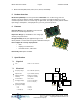
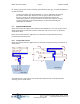
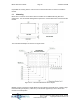
9.1 Mounting
MLink Ultra is a surface mount device which is installed on the OEM PCB along with other
components. The mechanical drawing below captures the external dimensions of the MLink Ultra
module.
Figure 9.1.1 – MLink Ultra Mechanical Drawing
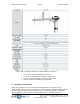
The recommended footprint is shown in the figure below.
Figure 9.1.2 – Recommended MLink Ultra Footprint
Minimal circuitry is required to support MLink Ultra and therefore the PCB can be a simple 2 layer
FR4 board with ground plane (> 1350 mm
2
) on the bottom opposite layer to the MLink Ultra
module for heat dissipation.