
Instruction Manual

4
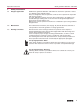
2. Technical data
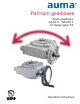
Features and functions
Version Standard: clockwise rotation RR, counterclockwise rotation LL, option: RL or LR
Housing material Standard: cast iron (GJL-250), Option: spheroidal cast iron (GJS-400-15)
Self-locking The gearboxes are self-locking when at stand-still under normal service conditions; strong
vibrations may cancel the self-locking effect. While in motion, safe breaking is not guaranteed. If
this is required, a separate brake must be used.
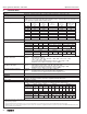
Output torques
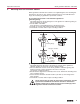
End stops Positive for both end positions by traveling nut, sensitive adjustment
Strength of end stop Guaranteed strength of end stop (in ft lbs.) for input side operation
Swing angle
GS 50.3 – GS 125.3
Standard: Fixed swing angle up to max. 100°; set in the factory to 92° unless ordered otherwise.
Options: Adjustable in steps of:
10°– 35°, 35° – 60°, 60° – 80°, 80° – 100°, 100° – 125°, 125° – 150°,
150° – 170°, 170° – 190°
For version with worm wheel made of bronze: swing angle > 190°,
Multi-turn version without end stops, version GSD
3)
Swing angle
GS 160.3 – GS 250.3
Standard: Adjustable 80° – 100°; set in the factory to 92° unless ordered otherwise.
Options: Adjustable in steps of: 20° – 40°, 40° – 60°, 60° – 80°,
For version with worm wheel made of bronze: swing angle
> 100°,
‘ Multi-turn version without end stops, version GSD
3)
Mechanical position indicator Standard: Pointer cover for continuous position indication
Options: Sealed pointer cover for horizontal outdoor installation
4)
Protection cover for buried service instead of pointer cover
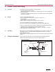
Input shaft Cylindrical with parallel key according to DIN 6885.1
Operation
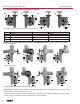
Motor operation With electric multi-turn actuator, directly or through primary reduction gearing VZ/GZ
Flanges for mounting of actuator, refer also to separate technical data sheets.
Type of duty According to actuator
Manual operation
5)
Via handwheel, directly or through primary reduction gearing VZ/GZ
Available handwheel diameters, selection according to the max. output torque:
25.4 mm correspond to 1 inch
1) With worm wheel made of spheroidal cast iron
2) Requires worm wheel made of bronze
3) Special sizing is required
4) For gas applications with sealed pointer cover, an air vent in the pointer cover or venting grooves in the valve mounting flange must be provided
5) Handwheel sizes shown reflect general industrial selection criteria. For information on gearbox/handwheel selection in accordance with AWWA Standard C504, please
refer to separate selection list/chart.
Worm gearboxes GS 50.3 – GS 250.3 Operation instructions
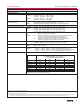
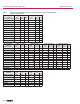
Type Output torques
100 % 140 % 175 %
1)
200 %
1)
Modulating torque
2)
max. ft lbs. max. ft lbs. max. ft lbs. max. ft lbs. max. ft lbs.
GS 50.3
184 258 – 369 92
GS 63.3
369 516 – 738 184
GS 80.3
738 1,033 – 1,475 369
GS 100.3
1,475 2,065 – 2,950 738
GS 125.3
2,950 4,130 – 5,900 1,475
GS 160.3
5,900 8,298 10,326 – 2,950
GS 200.3
11,801 16,595 20,652 – 5,900
GS 250.3
23,602 32,822 41,303 – 16,000
Type
GS 50.3 GS 63.3 GS 80.3 GS 100.3 GS 125.3
Reduction gearing – – – – VZ 2.3 VZ 3.3 VZ 4.3 – VZ 2.3 VZ 3.3 VZ 4.3
Handwheel Ø
mm
160
200
250
250
315
315
400
400
500
315
400
315
400
250
315
500
630
800
400
500
400
500
315
400
Type
GS 160.3 GS 200.3 GS 250.3
Reduction gearing – GZ 160.3 – GZ 200.3 – GZ 250.3
Handwheel Ø
mm
630
800
400 315 – 500
630
400 315 – 800
500
630
400
Type
GS 50.3 GS 63.3 GS 80.3 GS 100.3 GS 125.3
Reduction gearing – – – VZ 2.3 VZ 3.3 VZ 4.3 VZ 2.3 VZ 3.3 VZ 4.3
ft lbs. 185 330 330 370 185 370 185
Type
GS 160.3 GS 200.3 GS 250.3
Reduction gearing GZ 160.3 GZ 200.3 GZ 250.3
Reduction ratio 4:1 8:1 4:1 8:1 16:1 4:1 8:1 16:1
ft lbs. 370 330 370 370