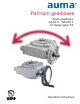
Part-turn gearboxes Worm gearboxes GS 50.3 – GS 250.
Worm gearboxes GS 50.3 – GS 250.3 Scope of these instructions: Operation instructions These operation instructions are valid for worm gearboxes of the type range GS 50.3 – GS 125.3 with primary reduction gearings VZ 2.3 – VZ 4.3. and GS 160.3 – GS 250.3 with primary reduction gearings GZ 160.3 – GZ 250.3. Table of contents 1. 1.1 1.2 1.3 2. 3. 3.1 3.2 3.3 4. 5. 6. 7. 8. 8.1 8.2 9. 9.1 9.2 10. 10.1 10.2 11. 12. 12.1 12.
Operation instructions Worm gearboxes GS 50.3 – GS 250.3 1. Safety instructions 1.1 Range of application AUMA worm gearboxes GS 50.3 – GS 250.3 are used for the operation of valves (e.g. butterfly valves and ball valves). They are designed for manual operation as well as motor operation in conjunction with electric actuators. For other applications, please consult us. The manufacturer is not liable for any possible damage resulting from use in other than the designated applications.
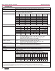
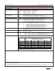
Worm gearboxes GS 50.3 – GS 250.3 2. Operation instructions Technical data Features and functions Version Housing material Self-locking Output torques Standard: clockwise rotation RR, counterclockwise rotation LL, option: RL or LR Standard: cast iron (GJL-250), Option: spheroidal cast iron (GJS-400-15) The gearboxes are self-locking when at stand-still under normal service conditions; strong vibrations may cancel the self-locking effect. While in motion, safe breaking is not guaranteed.
Operation instructions Primary reduction gearing Primary reduction gearing Valve attachment Valve attachment Splined coupling for connection to the valve shaft Service conditions Enclosure protection according to EN 60 5296) Corrosion protection Paint Color Ambient temperature Lifetime Worm gearboxes GS 50.3 – GS 250.3 Planetary gear with various reduction ratios for reducing the input torques Dimensions according to SP 101 Standard: GS 50.3 – GS 125.3: without spigot GS 160.3 – GS 250.
Worm gearboxes GS 50.3 – GS 250.
Operation instructions Worm gearboxes GS 50.3 – GS 250.3 3. Transport, storage and packaging 3.1 Transport 3.2 Storage .. . .. .. Transport to place of installation in sturdy packing. If mounted together with actuator: Attach ropes or hooks for the purpose of lifting by hoist only to the gearbox and not to the actuator. If eyebolts are supplied with the gearbox, they should be used to lift the gearbox only and not the valve Store in well-ventilated, dry room.
Worm gearboxes GS 50.3 – GS 250.3 5.
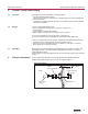
Operation instructions 6. Worm gearboxes GS 50.3 – GS 250.3 Mounting multi-turn actuators SA/SAR When gearboxes and multi-turn actuators are supplied together, the mounting has been done in the factory up to gearbox size GS 125.3. For sizes GS 160.3 and larger, the mounting of gearboxes is performed as follows. . . .. In case flange for actuator is not attached to gearbox or reduction gearing: Thoroughly degrease the mounting faces of the gearbox or reduction gearing as well as the flange for actuator.
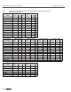
Worm gearboxes GS 50.3 – GS 250.3 Table 1: Operation instructions Bolts for mounting AUMA actuators to worm gearboxes/ primary reduction gearing (strength class min. 8.8) Worm gearbox/ primary reduction gearing SA(R) 07.1-FA10 Bolt Lock Qty. (UNC) washer GS 50.3 3/8-16x1 3/8 4 GS 63.3 3/8-16x1 3/8 4 GS 80.3 SA(R) 07.5-FA10 Bolt Lock Qty. (UNC) washer 3/8-16x1 3/8 4 3/8-16x1 3/8 4 3/8-16x1 3/8 4 3/8-16x1 3/8 4 GS 100.3 GS 100.3/VZ 3/8-16x1 3/8 4 GS 125.3 GS 125.3/VZ GS 160.
Operation instructions 7. Mounting to valve Worm gearboxes GS 50.3 – GS 250.3 AUMA worm gearboxes GS and primary reduction gearings VZ/GZ can be operated in any mounting position. For butterfly valves, the recommended mounting position is end position CLOSED (Prior to mounting, bring the gearbox to the mechanical end stop CLOSED by turning the handwheel clockwise).
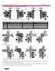
Worm gearboxes GS 50.3 – GS 250.3 8. Operation instructions Setting the end stops for manual operation If worm gearboxes GS are supplied on a valve the end stops are already set by the valve manufacturer. 8.1 Worm gearboxes on butterfly valves Setting end position CLOSED .. . . .. Remove all bolts (03) at limit stop housing (figures D, E). Turn valve manually to end position CLOSED. In case limit stop housing (10) has not yet rotated, turn it clockwise up to the stop.
Operation instructions 8.2 Worm gearboxes on ball valves Setting end position OPEN Setting end position CLOSED 9. 9.1 Worm gearboxes GS 50.3 – GS 250.3 In case end stops require adjustment, set end position OPEN first. If the exact end position of the valve cannot be seen through a position marking at the valve shaft, the setting may have to be done with the valve removed. Remove all bolts (03) at limit stop housing (10) (figures D, E). Turn valve manually to end position OPEN.
Worm gearboxes GS 50.3 – GS 250.3 Setting end position OPEN .. . .. . . Operation instructions Limit seating in end position CLOSED Turn back the valve from the end position by an amount equal to the overrun. Set limit switching according to the operation instructions SA/SAR. Check torque switching for end position CLOSED according to the operation instructions SA/SAR, and, if necessary, set to the required value. Torque seating in end position CLOSED Turn handwheel counterclockwise by approx.
Operation instructions Setting end position OPEN Switching off in end position OPEN Setting end position CLOSED .. . . . .. . . . Worm gearboxes GS 50.3 – GS 250.3 Remove all bolts (03) at limit stop housing (10) (figures F, G). Change to manual drive and move the valve manually to end position OPEN. In case limit stop housing (10) has not yet rotated, turn it counterclockwise up to the stop. Turn limit stop housing (10) back by ½ turn clockwise.
Worm gearboxes GS 50.3 – GS 250.3 10. Changing the swing angle Operation instructions The adjustment is made in end position OPEN. Optional for size GS 50.3 – GS 125.3 Standard for size GS 160.3 – GS 250.3 Accuracy: GS 50.3 – GS 125.3: GS 160.3 – GS 250.3: .. . 0.6° 0.11° to 0.14° 10.1 Changing the swing angle for sizes GS 50.3 – GS 125.3 (option) Unscrew protective cap (16) at limit stop housing (10) (figure H). Remove roll pin (020) with appropriate tool (available from AUMA).
Operation instructions Worm gearboxes GS 50.3 – GS 250.3 . . .. . .. .. .. . 10.2 Changing the swing angle for sizes GS 160.3 – GS 250.3 Remove all bolts (054) and pull off protective cap (16) (figure J). Remove screw (082) with washer (058) and setting ring (34). Increasing the swing angle Turn end stop nut (15) back counterclockwise. Move valve into the desired end position. Turn end stop nut (15) clockwise until it is tight up to the stop nut (7).
Worm gearboxes GS 50.3 – GS 250.3 Operation instructions 11. Enclosure protection IP 68 Definition According to EN 60 529, the conditions for meeting the requirements of enclosure protection IP 68 (requirements exceed those of IP 67) are to be agreed between manufacturer and user. AUMA worm gearboxes and primary reduction gearings in enclosure protection IP 68 meet the following requirements according to AUMA: .. ..
Operation instructions Worm gearboxes GS 50.3 – GS 250.3 12. Maintenance 12.1 General notes After commissioning, check worm gearbox for damage to paint finish. Do a thorough touch-up to prevent corrosion. Original paint in small quantities can be supplied by AUMA. AUMA worm gearboxes require only very little maintenance. To ensure that the worm gearbox is always ready to operate, we recommend for gearboxes operated less than 10 times per year, the following measures: . .. . .
Worm gearboxes GS 50.3 – GS 250.3 .. Operation instructions 12.2 Grease change for worm gearboxes GS 50.3 – GS 125.3 and primary reduction gearing VZ 2.3 – VZ 4.3 For gearboxes with multi-turn actuator: Remove multi-turn actuator. Remove gearbox from the valve: During this time, the valve/pipeline must not be under pressure! 12.2.1 Worm gearboxes Refer to spare parts list GS 50.3 – GS 125.3, page 24. Grease type, see name plate; grease quantities, see page 19, table 4. . . . . . . .. . .
Operation instructions Worm gearboxes GS 50.3 – GS 250.3 12.3 Grease change for worm gearboxes GS 160.3 – GS 250.3 and primary reduction gearing GZ 160.3 – GZ 250.3 .. For gearboxes with multi-turn actuator: Remove multi-turn actuator. Remove gearbox from the valve: During this time, the valve/pipeline must not be under pressure! 12.3.1 Worm gearboxes Refer to spare parts list GS 160.3 – GS 250.3, page 26. Grease type, see name plate; grease quantities, see page 19, table 4.
. . Worm gearboxes GS 50.3 – GS 250.3 Operation instructions Fill housing (001.0) with remaining grease and fit the complete housing cover with input drive shaft (003.0). Screw in bolts with lock washers and fasten them evenly crosswise to the appropriate torque according to table 2, page 11. Continue with section “After maintenance”, page 22. 12.3.3 Double-stage primary reduction gearing GZ 200.3 – GZ 250.3 (reduction ratio 16:1) Refer to spare parts list GZ 160.3 – GZ 250.3, page 28.
Operation instructions Worm gearboxes GS 50.3 – GS 250.3 13. Disposal and recycling AUMA gearboxes have an extremely long lifetime. However, they have to be replaced at one point in time. Our gearboxes have a modular design and may therefore easily be disassembled, separated and sorted according to materials, i.e.: .. . . . . various metals plastics greases and oils The following generally applies: Collect greases and oils during disassembly.
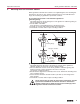
527.0 S1(073) 24 019.0 S1(009) S1(076) 523.0 S1(009) 518.0 517.0 022.0 525.0 S1(010) 519.1 S1(010) 526.0 S1(012) S1(011) S1(033) 045.0 521.1 524.0 S1(033) 520.0 520.0 520.0 021.0 534.0 S1(017) 522.0 S1(034) S1(009) S1(009) S1(017) 512.0 S1(009) S1(017) 522.0 020.0 512.0 512.0 Worm gearboxes GS 50.3 – GS 250.3 Operation instructions 15. Spare parts list worm gearboxes GS 50.3 – GS 125.3 and reduction gearing VZ 2.3 – VZ 4.
Operation instructions Worm gearboxes GS 50.3 – GS 250.3 Note: Please state type and commission no. of the device (see name plate) when ordering spare parts. Only original AUMA spare parts should be used. Delivered spare parts may slightly vary from the representation in these instructions. No. Designation Type 019.0 Housing VZ Sub-assembly 020.0 Housing cover VZ Sub-assembly 021.0 Input drive shaft VZ Sub-assembly 022.0 Planet carrier VZ Sub-assembly 045.
527.0 S1(073) 26 536.0 S1(056) 523.0 525.0 S1(010) 519.1 S1(010) 513.1 S1(009) 517.0 S1(012) S1(011) 518.0 524.0 526.0 538.1 538.0 521.1 S1(017) S1(009) 522.0 520.0 512.0 537.0 Worm gearboxes GS 50.3 – GS 250.3 Operation instructions 16. Spare parts list worm gearboxes GS 160.3 – GS 250.
Operation instructions Worm gearboxes GS 50.3 – GS 250.3 Note: Please state type and commission no. of the device (see name plate) when ordering spare parts. Only original AUMA spare parts should be used. Delivered spare parts may slightly vary from the representation in these instructions. No. Designation Type 512.0 Flange for actuator Sub-assembly 513.0 Grub screw Component 517.0 Housing Sub-assembly 518.0 Housing cover Sub-assembly 519.1 Worm wheel Component 520.
Worm gearboxes GS 50.3 – GS 250.3 Operation instructions 17. Spare parts list reduction gearings GZ 160.3 – GZ 250.3 (reduction ratios 4:1, 8:1 and 16:1) S1(003) 006.0 GZ 200.1 – GZ 250.1 16:1 GZ 160.1 – GZ 250.1 4:1 / 8:1 006.0 S1(003) S1(003) S1(003) 003.0 S1(004) S1(009) S1(029) 001.0 003.3 S1(004) S1(009) S1(029) 001.0 003.0 S1(014) 512.0 002.0 003.3 011.1 013.0 512.0 S1(014) 002.0 010.0 S1(003) 006.0 GZ 200.1 – GZ 250.1 16:1 S1(003) 003.0 S1(004) S1(009) S1(029) 001.0 003.
Operation instructions Worm gearboxes GS 50.3 – GS 250.3 Note: Please state type and commission no. of the device (see name plate) when ordering spare parts. Only original AUMA spare parts should be used. Delivered spare parts may slightly vary from the representation in these instructions. No. Designation 001.0 Housing Sub-assembly 002.0 Housing cover Sub-assembly 003.0 Housing cover Sub-assembly 003.3 Input drive shaft Sub-assembly 006.0 Planetary gear Sub-assembly 010.
Worm gearboxes GS 50.3 – GS 250.
Operation instructions Worm gearboxes GS 50.3 – GS 250.
North American Sales and Service: US Headquarters and Factory: AUMA Actuators, Inc. 100 Southpointe Blvd. Canonsburg PA 15317 Tel: 724-743-AUMA (2862) Fax: 724-743-4711 email: mailbox@auma-usa.com www.auma-usa.