
User guide

7. Electrical connection Work on the electrical system or equipment must only be
carried out by a skilled electrician himself or by specially
instructed personnel under the control and supervision of such
an electrician and in accordance with the applicable electrical
engineering rules.
7.1 Connection with AUMA plug/socket connector
.
Check whether type of current, supply voltage, and frequency comply with
motor data (refer to name plate at motor).
.
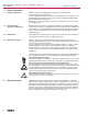
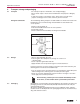
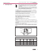
Loosen bolts (50.01) (figure 3) and remove plug cover.
.
Loosen screws (51.01) and remove socket carrier (51.0) from plug cover
(50.0).
.
Insert cable glands or conduit fittings suitable for connecting cables
(The enclosure protection stated on the name plate is only ensured if properly
sealed connections are made).
.
Seal cable entries which are not used with sealed threaded plugs.
.
Connect cables according to order-related terminal plan.
.
The terminal plan applicable to the actuator is placed inside the terminal
compartment, the operation instructions are attached to the handwheel in a
weather-proof bag.
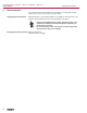
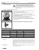
A special parking frame (figure C-2) for protection against touching the
uncoated contacts and against en
vironmental influences is available.
7.2 Delay time The delay time is the time from the tripping of the limit or torque switches to the
motor power being removed. To protect the valve and the actuator, we recom-
mend a delay time < 50 ms. Longer delay times are possible provided the oper-
ating time, output drive type, valve type, and the type of installation are consid
-
ered.
We recommend to switch off the corresponding contactor directly by the limit or
torque switch.
7.3
Reversal time Actuators oper
ated via non AUMA supplied controls must include a minimum
reversal time delay of 100ms.
Part-turn actuators SG 05.1 – SG 12.1 / SGR 05.1 – SGR 12.1
AUMA NORM Operation instructions
10
Figure C-1: Connection
50.0
50.01
51.0
51.01
Technical data Power terminals
1)
Protective earth Control terminals
No. of contacts max. 6 (3 are used) 1 (leading contact) 50 pins/sockets
Marking U1, V1, W1, U2, V2, W2 1 to 50
Connecting voltage max. 750 V
–
250 V
Current max. 25 A
–
16 A
Type of customer connection Screws Screw for ring lug Screws
Cross section max. 6 mm
2
(10 AWG) 6 mm
2
(10 AWG) 2.5 mm
2
(12 AWG)
Material: Pin/socket carrier Polyamide Polyamide Polyamide
Contacts Brass (Ms) Brass (Ms) Brass, tin plated or gold plated (option)
1) Suitable for copper wires. For aluminium wires, please contact AUMA
Table 2: Technical data AUMA plug/socket connector
Figure C-2: Parking frame
(accessory)
Parking frame