
User Manual

9. Setting the limit switching
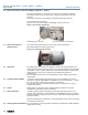
9.1 Setting the end position CLOSED (black section)
.
Turn handwheel clockwise until valve is closed.
.
After having reached the end position, turn back handwheel by approximately ½
a turn (overrun). During test run, check overrun and, if necessary, correct setting
of the limit switching.
.
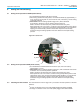
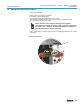
Press down and turn setting spindle A (figure K-1) with a flat blade
screw driver in direction of arrow, thereby observe pointer B.
While a ratchet is felt and heard, the pointer B moves 90° every time.
When pointer B is 90° from mark C, continue turning slowly. When pointer B has
reached the mark C, stop turning and release setting spindle. If you override the
tripping point inadvertently (ratchet is heard after the pointer has rotated),
continue turning the setting spindle in the same direction and repeat setting
process.
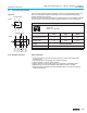
9.2 Setting the end position OPEN (white section)
.
Turn handwheel counterclockwise until valve is open, then turn back by
approximately ½ a turn.
.
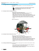
Press down and turn setting spindle D (figure K-1) with a flat blade screw driver
in direction of arrow, thereby observe pointer E.
While a ratchet is felt and heard, the pointer E moves 90° every time.
When pointer E is 90° from mark F, continue turning slowly. When pointer E has
reached the mark F, stop turning and release setting spindle. If you override the
tripping point inadvertently (ratchet is heard after the pointer has rotated),
continue turning the setting spindle in the same direction and repeat setting
process.
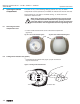
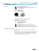
9.3 Checking the limit switches The red test buttons T and P (figure K-1) are used for manual operation of the limit
switches.
.
Turning T in direction of the arrow LSC (WSR) triggers limit switch CLOSED.
.
Turning P in direction of the arrow LSO (WÖL) triggers limit switch OPEN.
15
Multi-turn actuators SA 07.1 – SA 48.1 / SAR 07.1 – SAR 30.1
Operation instructions AUMA NORM
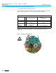
Figure K-1: Control unit
A
T
B
C
D
P
E
F