
User Manual
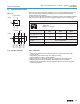
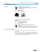
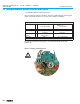

7.9 Limit and torque switches
Only the same potential can be switched on the two circuits (NC/NO contact) of a
limit or torque switch. If different potentials are to be switched simultaneously,
tandem switches are required.
To ensure correct actuator indications, the leading contacts of the tandem switches
must be used for that purpose and the lagging contacts for motor switching off.
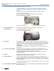
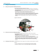
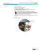
7.10 Fitting of the cover After connection:
.
Insert the socket carrier (51.0) into the plug cover (50.0) and fasten it with
screws (51.01).
.
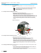
Clean sealing faces at the plug cover and the housing.
.
Check whether O-ring is in good condition.
.
Apply a thin film of non-acidic grease (e.g. Vaseline) to the sealing faces.
.
Replace plug cover (50.0) and fasten bolts (50.01) evenly crosswise.
.
Fasten conduit connections with the specified torque to ensure the required
enclosure protection.
13
Multi-turn actuators SA 07.1 – SA 48.1 / SAR 07.1 – SAR 30.1
Operation instructions AUMA NORM
Mechanical
lifetime = 2 x 10
6
starts
Type of current Switch rating I
max
30 V 125 V 250 V
1-phase AC
(ind. load) cos phi = 0,8
5 A 5 A 5 A
DC
(resistive load)
2 A 0,5 A 0.4 A
with gold plated
contacts
min. 5 V, max. 50 V
Current min. 4 mA, max. 400 mA
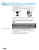
Table 5: Technical data for limit and torque switches
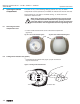
NO
NC
NC
N
O
RD
BK
RD
BK
BK 2
RD 2
BK
RD
BK 2
RD 2
BK
RD
TSC 1 / TSO 1
LSC 1 / LSO 1
TSC / TSO
L
SC /
L
SO
DSR 1 / DÖL 1
WSR 1 / WÖL 1
DSR / DÖL
WSR / WÖL
Figure G-5
II Tandem switch
SPDT
DPDT
I Single switch