
User Manual

7. Electrical connection Work on the electrical system or equipment must only be carried
out by a skilled electrician themselves or by specially instructed
personnel under the control and supervision of such an electrician
and in accordance with the applicable electrical engineering rules.
7.1 Connection with AUMA plug/socket connector
.
Check whether type of current, supply voltage, and frequency correspond to
motor data (refer to name plate at motor).
.
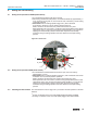
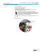
Loosen bolts (50.01) (figure G-1) and remove plug cover.
.
Loosen screws (51.01) and remove socket carrier (51.0) from plug cover (50.0).
.
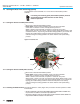
Insert cable glands or conduit fittings suitable for connecting cables.
(The enclosure protection stated on the name plate is only ensured if properly
sealed connections are made).
.
Seal cable entries which are not used with sealed threaded plugs.
.
Connect cables according to order-related terminal plan.
.
The terminal plan applicable to the actuator is placed inside the terminal
compartment, the operation instructions are attached to the handwheel in a
weather-proof bag.
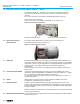
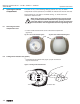
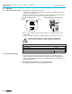
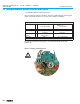
A special parking frame (figure G-2) for protection against touching the bare
contacts and against environmental influences is available.
11
Multi-turn actuators SA 07.1 – SA 48.1 / SAR 07.1 – SAR 30.1
Operation instructions AUMA NORM
Figure G-1: Connection
50.0
50.01
51.0
51.01
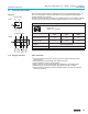
Technical data Power terminals
1)
Protective earth Control pins
No. of contacts max. 6 (3 are used) 1 (leading contact) 50 pins/sockets
Marking U1, V1, W1, U2, V2, W2 according to VDE 1 to 50
Voltage max. 750 V – 250 V
Nominal current max. 25 A –
16 A
Type of customer connection Screws Screw for ring lug Screws
Cross section max. 6 mm
2
(10 AWG) 6 mm
2
(10 AWG) 2.5 mm
2
(12 AWG)
Material: Pin/ socket carrier Polyamide
Polyamide Polyamide
Contacts Brass (Ms)
Brass (Ms)
Brass, tin plated or gold plated (option)
1) Suitable for copper wires. For aluminium wires it is necessary to contact AUMA.
From size SA(R) 25.1, the motor connection is realised via a separate terminal board
Table 4: Technical data AUMA plug/socket connectors
Figure G-2: Parking frame (accessory)
Parking frame