Electric multi-turn actuators SA 07.1 – SA 48.1 SAR 07.1 – SAR 30.
Multi-turn actuators SA 07.1 – SA 48.1 / SAR 07.1 – SAR 30.1 AUMA NORM Scope of these instructions: These instructions are valid for multi-turn actuators of the type range SA 07.1 – SA 48.1 and SAR 07.1 – SAR 30.1 in version AUMA NORM. These operation instructions are only valid for “clockwise closing”, i.e. driven shaft turns clockwise to close the valve. Table of contents 1. Safety instructions 1.1 Range of application 1.2 Commissioning (electrical connection) 1.3 Maintenance 1.4 Warnings and notes 2.
Operation instructions 15. 16. 17. 18. 19. 20. 21. 22. 23. Multi-turn actuators SA 07.1 – SA 48.1 / SAR 07.1 – SAR 30.1 AUMA NORM Setting the mechanical position indicator (option) Closing the switch compartment Enclosure protection IP 68 (option) Maintenance Lubrication Disposal and recycling Service Spare parts list Multi-turn actuator SA(R) 07.1 – SA(R) 16.1 with plug/socket connector Spare parts list Multi-turn actuator SA 25.1 – SA 48.1/SAR 25.1 – SAR 30.
Multi-turn actuators SA 07.1 – SA 48.1 / SAR 07.1 – SAR 30.1 AUMA NORM Operation instructions 1. Safety instructions 1.1 Range of application AUMA actuators are designed for the operation of industrial valves, e.g. globe valves, gate valves, butterfly valves and ball valves. For other applications, please consult us. The manufacturer is not liable for any possible damage resulting from use in other than the designated applications. Such risk lies entirely with the user.
Operation instructions 3. Multi-turn actuators SA 07.1 – SA 48.1 / SAR 07.1 – SAR 30.1 AUMA NORM Technical data Table 1: Multi-turn actuator SA 07.1 – SA 48.1 /SAR 07.1 – SAR 30.1 Multi-turn actuators AUMA NORM require electric controls. AUMA offers the controls AUMA MATIC AM or AUMATIC AC for the sizes SA(R) 07.1 - SA(R) 16.1. These can also easily be mounted to the actuator at a later date.
Multi-turn actuators SA 07.1 – SA 48.1 / SAR 07.1 – SAR 30.
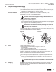
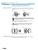
Multi-turn actuators SA 07.1 – SA 48.1 / SAR 07.1 – SAR 30.1 AUMA NORM Operation instructions .. . 4. Transport, storage and packaging 4.1 Transport Fitting the handwheel: For transport to place of installation, use sturdy packaging. Do not attach ropes or hooks to the handwheel for the purpose of lifting by hoist. If multi-turn actuator is mounted on valve, attach ropes or hooks for the purpose of lifting by hoist to valve and not to multi-turn actuator.
Multi-turn actuators SA 07.1 – SA 48.1 / SAR 07.1 – SAR 30.1 AUMA NORM Operation instructions We use the following packaging materials: wood, cardboard, paper and Polyurethane foam. For the disposal of the packaging material, we recommend recycling and collection centers. 5. Mounting to valve/gearbox . . Prior to mounting the multi-turn actuator must be checked for damage. Damaged parts must be replaced by original spare parts. After mounting, check multi-turn actuator for damage to paint finish.
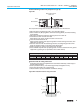
Multi-turn actuators SA 07.1 – SA 48.1 / SAR 07.1 – SAR 30.1 AUMA NORM Operation instructions Finish machining of stem nut (output drive type A): Figure B-1 Output drive type A Stem nut 80.3 80.01/80.02 80.2 .. .. .. . .. The output drive flange does not have to be removed from the actuator. Remove spigot ring (80.2, figure B-1) from mounting flange. Take off stem nut (80.3) together with thrust bearing (80.01) and thrust bearing races (80.02).
Multi-turn actuators SA 07.1 – SA 48.1 / SAR 07.1 – SAR 30.1 AUMA NORM 6. Manual operation Engaging manual operation: Operation instructions The actuator may be operated manually for purposes of setting and commissioning, and in case of motor failure or power failure. Manual operation is engaged by an internal change-over mechanism. . Lift up change-over lever in the center of the handwheel to approx. 85°, while slightly turning the handwheel back and forth until manual operation engages (figure C).
Multi-turn actuators SA 07.1 – SA 48.1 / SAR 07.1 – SAR 30.1 AUMA NORM Operation instructions 7. Electrical connection 7.1 Connection with AUMA plug/socket connector Work on the electrical system or equipment must only be carried out by a skilled electrician themselves or by specially instructed personnel under the control and supervision of such an electrician and in accordance with the applicable electrical engineering rules. . .. . .. . Figure G-1: Connection 50.0 50.01 51.0 51.
Multi-turn actuators SA 07.1 – SA 48.1 / SAR 07.1 – SAR 30.1 AUMA NORM 7.2 Operation instructions Motor connection for the sizes SA(R) 25.1/SAR 30.1 – SA 48.1. From the size SA(R) 25.1, the power for the motor is connected to separate terminals. For this, the cover at the motor connection compartment has to be removed. The control contacts are connected to the AUMA plug/socket connector.
Multi-turn actuators SA 07.1 – SA 48.1 / SAR 07.1 – SAR 30.1 AUMA NORM Operation instructions 7.9 Limit and torque switches Only the same potential can be switched on the two circuits (NC/NO contact) of a limit or torque switch. If different potentials are to be switched simultaneously, tandem switches are required. To ensure correct actuator indications, the leading contacts of the tandem switches must be used for that purpose and the lagging contacts for motor switching off.
Multi-turn actuators SA 07.1 – SA 48.1 / SAR 07.1 – SAR 30.1 AUMA NORM 8. Opening the switch compartment Operation instructions To be able to carry out the following settings (sections 9. to 15.), the switch compartment must be opened and, if installed, the indicator disc must be removed. These settings are only valid for “clockwise closing”, i.e. driven shaft turns clockwise to close the valve.
Multi-turn actuators SA 07.1 – SA 48.1 / SAR 07.1 – SAR 30.1 AUMA NORM Operation instructions 9. Setting the limit switching 9.1 Setting the end position CLOSED (black section) .. . Turn handwheel clockwise until valve is closed. After having reached the end position, turn back handwheel by approximately ½ a turn (overrun). During test run, check overrun and, if necessary, correct setting of the limit switching.
Multi-turn actuators SA 07.1 – SA 48.1 / SAR 07.1 – SAR 30.1 AUMA NORM Operation instructions 10. Setting the DUO limit switching (option) Any application can be switched on or off via the two intermediate position switches. For setting, the switching point (intermediate position) must be approached from the same direction as later during electrical operation. .. 10.1 Setting the direction CLOSE (black section) Move valve to desired intermediate position.
Multi-turn actuators SA 07.1 – SA 48.1 / SAR 07.1 – SAR 30.1 AUMA NORM Operation instructions 11. Setting the torque switching .. 11.1 Setting The set torque must suit the valve! This setting should only be changed with the consent of the valve manufacturer! Figure L: Torque switching heads indication in ft lbs Setting CLOSED Setting OPEN Ft. Lbs Ft. Lbs 45 .. . 35 25 45 15 P O 15 25 35 Loosen both lock screws O at the torque dial (figure L).
Multi-turn actuators SA 07.1 – SA 48.1 / SAR 07.1 – SAR 30.1 AUMA NORM 12. Test run 12.1 Check direction of rotation . . Operation instructions If provided, place indicator disc on shaft. The direction of rotation of the indicator disc (figure M-1) indicates the direction of rotation of the output drive. If there is no indicator disc, the direction of rotation can also be observed on the hollow shaft. For this, remove screw plug (no. 27) (figure M-2).
Multi-turn actuators SA 07.1 – SA 48.1 / SAR 07.1 – SAR 30.1 AUMA NORM Operation instructions 13. Setting the potentiometer (option) .. . . – For remote indication – . Move valve to end position CLOSED. If installed, pull off indicator disc. Turn potentiometer (E2) clockwise until stop is felt. End position CLOSED corresponds to 0 %, end position OPEN to 100 %. Turn potentiometer (E2) back a little.
Multi-turn actuators SA 07.1 – SA 48.1 / SAR 07.1 – SAR 30.1 AUMA NORM Operation instructions 14. Setting the electronic position transmitter RWG (option) – For remote indication or external controls – After mounting the multi-turn actuator to the valve, check setting by measuring the output current (see sections 14.1 or 14.2) and re-adjust, if necessary. Table 7: Technical data RWG 4020 Terminal plans KMS TP_ _ 4 / _ _ _ 3- or 4-wire system Output current Power supply max. input current max.
Multi-turn actuators SA 07.1 – SA 48.1 / SAR 07.1 – SAR 30.1 AUMA NORM Operation instructions .. .. 14.1 Setting for 2-wire system 4 – 20 mA and 3-/4-wire system 0 – 20 mA .. Connect voltage to electronic position transmitter. Move valve to end position CLOSED. If installed, pull off indicator disc. Connect ammeter for 0 – 20 mA to measuring points (figure P-2). The circuit (external load) must be connected (max.
Multi-turn actuators SA 07.1 – SA 48.1 / SAR 07.1 – SAR 30.1 AUMA NORM Operation instructions .. .. 14.2 Setting the 3-/4- wire system 4 – 20 mA Connect voltage to electronic position transmitter. Move valve to end position CLOSED. If installed, pull off indicator disc. Connect ammeter for 0 – 20 mA to measuring points (figure P-2). .. The circuit (external load) must be connected (max.
Multi-turn actuators SA 07.1 – SA 48.1 / SAR 07.1 – SAR 30.1 AUMA NORM Operation instructions 15. Setting the mechanical position indicator (option) .. . .. Place indicator disc on shaft. Move valve to end position CLOSED. Turn lower indicator disc (figure Q1) until symbol CLOSED is in alignment with the mark on the cover (figure Q-2). Move actuator to end position OPEN. Hold lower indicator disc CLOSED in position and turn upper disc with symbol OPEN until it is in alignment with the mark on the cover.
Multi-turn actuators SA 07.1 – SA 48.1 / SAR 07.1 – SAR 30.1 AUMA NORM Operation instructions 17. Enclosure protection IP 68 (option) Definition According to EN 60 259, the conditions for meeting the requirements of enclosure protection IP 68 are to be agreed between manufacturer and user. AUMA actuators and controls in enclosure protection IP 68 meet the following requirements according to AUMA: Duration of submersion in water max. 72 hours Head of water max.
Multi-turn actuators SA 07.1 – SA 48.1 / SAR 07.1 – SAR 30.1 AUMA NORM Operation instructions 18. Maintenance After maintenance, check multi-turn actuator for damage to paint finish. If damage to paint-finish has occurred, it has to be touched up to avoid corrosion. Original paint in small quantities can be supplied by AUMA. AUMA multi-turn actuators require low-level maintenance. Precondition for reliable service is correct commissioning.
Multi-turn actuators SA 07.1 – SA 48.1 / SAR 07.1 – SAR 30.1 AUMA NORM Operation instructions 20. Disposal and recycling AUMA actuators have an extremely long lifetime. However, they have to be replaced at one point in time. The actuators have a modular design and may therefore easily be disassembled, separated, and sorted according to materials, i.e.: .. .. . . . electronic scrap various metals plastics greases and oils The following generally applies: Collect greases and oils during disassembly.
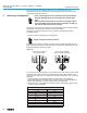
S2 15.0 S1 / S2 7.1 – SA 14.1 07.1 – SAR 14.1 6.1 16.1 70.0 79.0 70.1 54.0 60.0 49.0 61.0 20.0 57.0 56.0 53.0 59.0 S1 / S2 S2 S2 156.0 S2 S2 79.0 106.0 105.0 100 107 1.0 25.0 019 020 24.0 / 23.0 22.0 52.0 51.0 18 19.0 17.0 B1 / C 053 S2 24 S1 / S2 S2 S2 S2 6 2.0 3.0 5.32 5.7 S2 5.12 S1 / S2 39 S1 / S2 27 58.0 55.0 50.0 A 160.1 160.2 5.0 S2 80.001 80.3 80.001 80.0 5.37 5.8 151.0 D 152.1 152.2 90.001 90.001 9.0 AUMA ACTUATORS INC.
Multi-turn actuators SA 07.1 – SA 48.1 / SAR 07.1 – SAR 30.1 AUMA NORM Operation instructions Notes: When placing orders for spare parts, it is essential to mention type of actuator and our commission number (refer to actuator name plate). Delivered spare parts may slightly vary from the representation in these instructions. No. Type Designation 012 E Notched pin 019 E Cheese head screw 020 E Clamping washer 053 No. Type Designation 58.0 B 59.
AUMA ACTUATORS INC. PITTSBURGH PA USA SA 07.1-FA10 Com no:1309533 No: 3302MD 19302 n: 11 rpm T open: 7-22Nm T close 7-22Nm Lubr.: F1 NEMA4 Temp -25°C/+80°C Sample name plate - Actuator type - Commission number - Comm./ sales order number Works/ Serial number - Protection type Torque range in CLOSE/ OPEN - Lubricant - Temperature range Operation instructions Multi-turn actuators SA 07.1 – SA 48.1 / SAR 07.1 – SAR 30.1 AUMA NORM 23. Spare parts list Multi-turn actuator SA 25.1 – SA 48.1/SAR 25.1 – SAR 30.
Multi-turn actuators SA 07.1 – SA 48.1 / SAR 07.1 – SAR 30.1 AUMA NORM Operation instructions Notes: When placing orders for spare parts, it is essential to mention type of actuator and our commission number (refer to actuator name plate). Delivered spare parts may slightly vary from the representation in these instructions. No. Type Designation No. Type Designation 1.026 E Quad ring / radial seal 54.0 B Socket for motor 1.038 E O-ring 55.0 B Socket for protective earth 1.
Multi-turn actuators SA 07.1 – SA 48.1 / SAR 07.1 – SAR 30.
North American Sales and Service: US Headquarters and Factory: AUMA Actuators, Inc. 100 Southpointe Blvd. Canonsburg PA 15317 Tel: 724-743-AUMA (2862) Fax: 724-743-4711 email: mailbox@auma-usa.com www.auma-usa.