
Owner manual

2
Multi-turn actuators SA 07.1 – SA 30.1/ SAR 07.1 – SAR 30.1
with actuator controls AUMA MATIC AM 01.1 / AM 02.1 Operation instructions
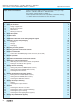
Table of contents Page
1. Safety instructions 4
1.1 Range of application 4
1.2 Electrical connection 4
1.3 Maintenance 4
1.4 Warnings and notes 4
2. Short description 5
3. Technical data 6
4. Additional information to the wiring diagram legend 9
5. Transport, storage and packaging 10
5.1 Transport 10
5.2 Storage 10
5.3 Packaging 11
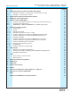
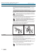
6. Mounting to valve/ gearbox 12
7. Mounting positions of the local controls 14
8. Electrical connection 15
8.1 Connection with AUMA plug/ socket connector (S, SH, SE) 17
9. Manual operation 19
10. Operation and indications of the local controls 20
11. Opening the switch compartment 22
11.1 Removing the cover from the switch compartment 22
11.2 Pulling off the indicator disc (option) 22
12. Setting the limit switching 23
12.1 Setting end position CLOSED (black section) 23
12.2 Setting end position OPEN (white section) 23
12.3 Checking the limit switches 23
13. Setting the DUO limit switching (option) 24
13.1 Setting direction CLOSE (black section) 24
13.2 Setting direction OPEN (white section) 24
13.3 Checking the DUO limit switches 24
14. Setting the torque switching 25
14.1 Setting 25
14.2 Checking the torque switches 25
15. Test run 26
15.1 Checking the direction of rotation 26
15.2 Checking the setting of the limit switching 27
15.3 Checking the type of seating 27
15.4 Checking the PTC tripping device (option) 27
16. Setting the potentiometer (option) 29
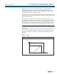
Scope of these instructions:
These instructions valid for multi-turn actuators of the type range
SA 07.1 – SA 30.1/ SAR 07.1 – SAR 30.1 with
the actuator controls AM 01.1 / AM 02.1.
These operation instructions are only valid for “clockwise closing”,
i.e. driven shaft turns clockwise to close the valve.