
Owner manual


Finish machining of stem nut (output drive type A):
The output drive flange does not have to be removed from the actuator.
.
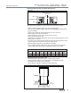
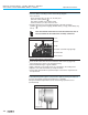
Remove spigot ring (80.2, figure C-1) from mounting flange.
.
Take off stem nut (80.3) together with thrust bearing (80.01) and thrust bear-
ing races (80.02).
.
Remove thrust bearing and thrust bearing races from stem nut.
.
Drill and bore stem nut and cut thread.
When fixing in the chuck, make sure stem nut runs true!
.
Clean the machined stem nut.
.
Apply Lithium soap EP multi-purpose grease to thrust bearing and races, then
place them on stem nut.
.
Re-insert stem nut with thrust bearings into the mounting flange. Ensure that
dogs are placed correctly in the slots of the hollow shaft.
.
Screw in spigot ring until it is firm against the shoulder.
.
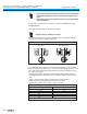
Press Lithium soap EP multi-purpose grease on mineral oil base into the
grease nipple with a grease gun (for quantities, please refer to table):
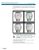
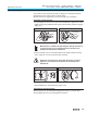
Protection tube for rising valve stem
.
Seal thread with hemp, Teflon tape, or thread sealing material.
.
Screw protection tube (1) into thread (figure C-2) and tighten it firmly.
.
Push down the sealing (2) to the housing.
.
Check whether cap (3) is available and without damage.
Multi-turn actuators SA 07.1 – SA 30.1/ SAR 07.1 – SAR 30.1
Operation instructions with actuator controls AUMA MATIC AM 01.1 / AM 02.1
13
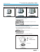
Output
drive
A 07.2 A 10.2 A 14.2 A 16.2 A 25.2 A 30.2 A 35.2 A 40.2 A 48.2
Qty
1)
1.5 g 2 g 3 g 5 g 10 g 14 g 20 g 25 g 30 g
1) For greases with a density ρ = 0.9 kg/dm³
3
; conversion factor: 1 oz corresponds to 28.35 g
Table 2: Grease quantities for output drive type A
3
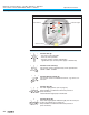
1
2
Figure C-1
80.3
80.2
Output drive type A
Stem nut
80.01/80.02
Figure C-2: Protection tube for rising valve stem