Electric multi-turn actuators SA 07.1 – SA 30.1 SAR 07.1 – SAR 30.1 with actuator controls AUMA MATIC AM 01.1 / AM 02.
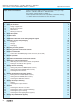
Multi-turn actuators SA 07.1 – SA 30.1/ SAR 07.1 – SAR 30.1 with actuator controls AUMA MATIC AM 01.1 / AM 02.1 Scope of these instructions: Operation instructions These instructions valid for multi-turn actuators of the type range SA 07.1 – SA 30.1/ SAR 07.1 – SAR 30.1 with the actuator controls AM 01.1 / AM 02.1. These operation instructions are only valid for “clockwise closing”, i.e. driven shaft turns clockwise to close the valve. Table of contents Page 1. Safety instructions 1.
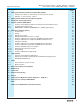
Operation instructions Multi-turn actuators SA 07.1 – SA 30.1/ SAR 07.1 – SAR 30.1 with actuator controls AUMA MATIC AM 01.1 / AM 02.1 Page 17. Setting the electronic position transmitter RWG (option) 17.1 Setting 2-wire system 4 – 20 mA and 3- /4-wire system 0 – 20 mA 17.2 Setting 3- / 4- wire system 4 – 20 mA 30 31 32 18. Setting the mechanical position indicator (option) 33 19. Closing the switch compartment 33 20. Actuator controls AUMA MATIC 20.
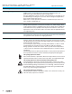
Multi-turn actuators SA 07.1 – SA 30.1/ SAR 07.1 – SAR 30.1 with actuator controls AUMA MATIC AM 01.1 / AM 02.1 1. Safety instructions 1.1 Range of application Operation instructions AUMA actuators are designed for the operation of industrial valves, e.g. globe valves, gate valves, butterfly valves and ball valves. For other applications, please consult us. The manufacturer is not liable for any possible damage resulting from use in other than the designated applications.
Operation instructions 2. Multi-turn actuators SA 07.1 – SA 30.1/ SAR 07.1 – SAR 30.1 with actuator controls AUMA MATIC AM 01.1 / AM 02.1 Short description AUMA multi-turn actuators of the type range SA 07.1 – SA 30.1/SAR 07.1 – SAR 30.1 are driven by an electric motor and controlled by the actuator controls AUMA MATIC AM 01.1/ AM 02.1, which is included in the scope of delivery. A handwheel is provided for manual operation. The limitation of travel is realized via limit switches in both end positions.
Multi-turn actuators SA 07.1 – SA 30.1/ SAR 07.1 – SAR 30.1 with actuator controls AUMA MATIC AM 01.1 / AM 02.1 3.
Multi-turn actuators SA 07.1 – SA 30.1/ SAR 07.1 – SAR 30.1 with actuator controls AUMA MATIC AM 01.1 / AM 02.
Multi-turn actuators SA 07.1 – SA 30.1/ SAR 07.1 – SAR 30.1 with actuator controls AUMA MATIC AM 01.1 / AM 02.1 Operation instructions Threads for cable glands Standard: NPT-threads Options: Pg-threads, G-threads Wiring diagram Wiring diagram according to commission number included in delivery Further options for version with RWG in the actuator Position feedback (option) Analogue output E2 = 0/4 – 20 mA (load max.
Operation instructions 4. Multi-turn actuators SA 07.1 – SA 30.1/ SAR 07.1 – SAR 30.1 with actuator controls AUMA MATIC AM 01.1 / AM 02.1 Additional information to the wiring diagram legend Information A: A running indication is possible if blinker transmitter (S5) is installed (opening and closing of contacts). Direction CLOSE: Connections XK 6 - XK 7 Direction OPEN: Connections XK 6 - XK 8 Contacts remain closed in end position.
Multi-turn actuators SA 07.1 – SA 30.1/ SAR 07.1 – SAR 30.1 with actuator controls AUMA MATIC AM 01.1 / AM 02.1 5. Transport, storage and packaging 5.1 Transport Operation instructions .. . For transport to place of installation, use sturdy packaging. Do not attach ropes or hooks to the handwheel for the purpose of lifting by hoist. If multi-turn actuator is mounted on valve, attach ropes or hooks for the purpose of lifting by hoist to valve and not to multi-turn actuator.
Operation instructions 5.3 Multi-turn actuators SA 07.1 – SA 30.1/ SAR 07.1 – SAR 30.1 with actuator controls AUMA MATIC AM 01.1 / AM 02.1 Packaging Our products are protected by special packaging for the transport ex works. The packaging consists of environmentally friendly materials which can easily be separated and recycled. We use the following packaging materials: wood, cardboard, paper, and Polyurethane foam. For the disposal of the packaging material, we recommend recycling and collection centers.
Multi-turn actuators SA 07.1 – SA 30.1/ SAR 07.1 – SAR 30.1 with actuator controls AUMA MATIC AM 01.1 / AM 02.1 6. Mounting to valve/ gearbox . . Operation instructions Prior to mounting the multi-turn actuator must be checked for damage. Damaged parts must be replaced by original spare parts. After mounting to valve/ gearbox, touch up any possible damage to paint finish. The multi-turn actuator leaves the factory in position CLOSED (limit switch CLOSED tripped). .
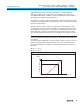
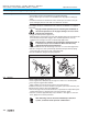
Multi-turn actuators SA 07.1 – SA 30.1/ SAR 07.1 – SAR 30.1 with actuator controls AUMA MATIC AM 01.1 / AM 02.1 Operation instructions Finish machining of stem nut (output drive type A): Figure C-1 Output drive type A Stem nut 80.3 80.01/80.02 80.2 The output drive flange does not have to be removed from the actuator. .. .. .. . .. Remove spigot ring (80.2, figure C-1) from mounting flange. Take off stem nut (80.3) together with thrust bearing (80.01) and thrust bearing races (80.02).
Multi-turn actuators SA 07.1 – SA 30.1/ SAR 07.1 – SAR 30.1 with actuator controls AUMA MATIC AM 01.1 / AM 02.1 7. Operation instructions Mounting positions of the local controls The mounting position of the local controls is designed according to the order. If, after mounting the actuator to the valve or the gearbox on site, the local controls is in an unfavorable position, the mounting position can easily be changed at a later date.
Multi-turn actuators SA 07.1 – SA 30.1/ SAR 07.1 – SAR 30.1 with actuator controls AUMA MATIC AM 01.1 / AM 02.1 Operation instructions 8. Electrical connection Work on the electrical system or equipment must only be carried out by a skilled electrician themselves or by specially instructed personnel under the control and supervision of such an electrician and in accordance with the applicable electrical engineering rules.
Multi-turn actuators SA 07.1 – SA 30.1/ SAR 07.1 – SAR 30.1 with actuator controls AUMA MATIC AM 01.1 / AM 02.1 Operation instructions Actuator controls on wall bracket (accessory) For version on wall bracket, please observe the following: Figure E: AUMA MATIC on wall bracket Connecting cables to actuator . . . .. Versions with potentiometer in the actuator are not suitable.
Multi-turn actuators SA 07.1 – SA 30.1/ SAR 07.1 – SAR 30.1 with actuator controls AUMA MATIC AM 01.1 / AM 02.1 Operation instructions 8.1 Connection with AUMA plug/ socket connector (S, SH, SE) Figure F-1: Version SH (standard) Figure F-2: Version S Figure F-3: Version SE Before mains connection Check whether type of current, supply voltage, and frequency comply with motor data (refer to name plate at motor): VD00 63-4/45 Art. No.: Z006.413 3 ~ 480V 60Hz 0.09 kW Y 0.
Multi-turn actuators SA 07.1 – SA 30.1/ SAR 07.1 – SAR 30.1 with actuator controls AUMA MATIC AM 01.1 / AM 02.1 Operation instructions . Connecting the cables Connect cables according to order-related wiring diagram. Cross sections: - Power terminals (U1, V1, W1, U2, V2, W2) and protective earth (symbol: ) max. 6 mm² flexible, max. 10 mm² solid - Control contacts (1 to 50) = max. 2.
Multi-turn actuators SA 07.1 – SA 30.1/ SAR 07.1 – SAR 30.1 with actuator controls AUMA MATIC AM 01.1 / AM 02.1 Operation instructions 9. Manual operation The actuator may be operated manually for purposes of setting and commissioning and in case of motor failure or power failure. Manual operation is engaged by an internal change-over mechanism. . Engaging manual operation Lift up change-over lever in the center of the handwheel to approx.
Multi-turn actuators SA 07.1 – SA 30.1/ SAR 07.1 – SAR 30.1 with actuator controls AUMA MATIC AM 01.1 / AM 02.1 Operation instructions 10. Operation and indications of the local controls Figure M: Local controls Push buttons Indication lights Selector switch Selector switch 0 I 0 I I 0 20 I Position Remote control (II): The actuator can be controlled from remote, e.g. via the control room.
Multi-turn actuators SA 07.1 – SA 30.1/ SAR 07.1 – SAR 30.1 with actuator controls AUMA MATIC AM 01.1 / AM 02.1 Operation instructions Push buttons If the selector switch is in position local control (I), use the push buttons OPEN STOP - CLOSE to operate the actuator locally. OPEN: Actuator runs in direction OPEN STOP: Actuator stops CLOSE: Actuator runs in direction CLOSE The operation commands OPEN - CLOSE can be used for control during push-to-run operation or in the self-retaining mode.
Multi-turn actuators SA 07.1 – SA 30.1/ SAR 07.1 – SAR 30.1 with actuator controls AUMA MATIC AM 01.1 / AM 02.1 Operation instructions 11. Opening the switch compartment To be able to carry out the following settings (up to and including clause 18.), the switch compartment must be opened and, if installed, the indicator disc must be removed. These settings are only valid for “clockwise closing”, i.e. driven shaft turns clockwise to close the valve.
Multi-turn actuators SA 07.1 – SA 30.1/ SAR 07.1 – SAR 30.1 with actuator controls AUMA MATIC AM 01.1 / AM 02.1 Operation instructions 12. Setting the limit switching 12.1 Setting end position CLOSED (black section) .. . Turn handwheel clockwise until valve is closed. Turn handwheel back by approximately half a turn (overrun). During test run check overrun and, if necessary, correct setting of the limit switching.
Multi-turn actuators SA 07.1 – SA 30.1/ SAR 07.1 – SAR 30.1 with actuator controls AUMA MATIC AM 01.1 / AM 02.1 Operation instructions 13. Setting the DUO limit switching (option) Any application can be switched on or off via the two intermediate position switches. For setting, the switching point (intermediate position) must be approached from the same direction as later during electrical operation. .. 13.1 Setting direction CLOSE (black section) Move valve to desired intermediate position.
Multi-turn actuators SA 07.1 – SA 30.1/ SAR 07.1 – SAR 30.1 with actuator controls AUMA MATIC AM 01.1 / AM 02.1 Operation instructions 14. Setting the torque switching .. 14.1 Setting The set torque must suit the valve! This setting must only be changed with the consent of the valve manufacturer! Figure Q: Torque switching heads Setting OPEN Setting CLOSED Ft. Lbs Ft. Lbs 45 .. . 35 25 45 15 P O 15 25 35 Loosen both lock screws O at the torque dial (figure Q).
Multi-turn actuators SA 07.1 – SA 30.1/ SAR 07.1 – SAR 30.1 with actuator controls AUMA MATIC AM 01.1 / AM 02.1 Operation instructions 15. Test run 15.1 Checking the direction of rotation . . If provided, place indicator disc on shaft. The direction of rotation of the indicator disc (figure R-1) indicates the direction of rotation of the output drive. If there is no indicator disc, the direction of rotation can also be observed on the hollow shaft. For this purpose, remove screw plug (no.
Multi-turn actuators SA 07.1 – SA 30.1/ SAR 07.1 – SAR 30.1 with actuator controls AUMA MATIC AM 01.1 / AM 02.1 Operation instructions . 15.2 Checking the setting of the limit switching Set selector switch to position OFF (0) (figure U-1). Figure U-1: Selector switch OFF The controls’ power supply is maintained in position OFF. .. Move actuator manually into both end positions of the valve. Check if limit switching is set correctly for both end positions.
Multi-turn actuators SA 07.1 – SA 30.1/ SAR 07.1 – SAR 30.1 with actuator controls AUMA MATIC AM 01.1 / AM 02.1 Operation instructions In case the selector switch position TEST does not initiate a fault signal, the wiring and the selector switch have to be checked by the AUMA service. . If no other options (clauses 16. to 18.) require setting: Close switch compartment (see page 33, clause 19.).
Multi-turn actuators SA 07.1 – SA 30.1/ SAR 07.1 – SAR 30.1 with actuator controls AUMA MATIC AM 01.1 / AM 02.1 Operation instructions 16. Setting the potentiometer (option) — For remote indication — .. . . Move valve to end position CLOSED. Turn potentiometer (E2) clockwise to the stop. End position CLOSED corresponds to 0 %, end position OPEN to 100 %. Turn potentiometer (E2) slightly back.
Multi-turn actuators SA 07.1 – SA 30.1/ SAR 07.1 – SAR 30.1 with actuator controls AUMA MATIC AM 01.1 / AM 02.1 Operation instructions 17. Setting the electronic position transmitter RWG (option) — For remote indication or external control — After mounting the actuator on the valve, check setting and adjust, if necessary (refer to subclauses 17.1 or 17.2). Table 3: Technical data RWG 4020 KMS TP_ _ 4 / _ _ _ Terminal plans Output current Power supply Max. input current Max.
Multi-turn actuators SA 07.1 – SA 30.1/ SAR 07.1 – SAR 30.1 with actuator controls AUMA MATIC AM 01.1 / AM 02.1 Operation instructions 17.1 Setting 2-wire system 4 – 20 mA and 3- /4-wire system 0 – 20 mA .. . .. Connect voltage to electronic position transmitter via AM. Move valve to end position CLOSED. Connect ammeter for 0 – 20 mA to measuring points (figure Y-1). The circuit (external load) must be connected (observe max.
Multi-turn actuators SA 07.1 – SA 30.1/ SAR 07.1 – SAR 30.1 with actuator controls AUMA MATIC AM 01.1 / AM 02.1 Operation instructions 17.2 Setting 3- / 4- wire system 4 – 20 mA .. . .. Connect voltage to electronic position transmitter via AM. Move valve to end position CLOSED. Connect ammeter for 0 – 20 mA to measuring points (figure Y-2). The circuit (external load) must be connected (observe max.
18. Setting the mechanical position indicator (option) .. . .. Place indicator disc on shaft. Move valve to end position CLOSED. Turn lower indicator disc (figure Z-1) until symbol CLOSED is in alignment with the mark on the cover (figure Z-2). Move actuator to end position OPEN. Hold lower indicator disc CLOSED in position and turn upper disc with symbol OPEN until it is in alignment with the mark on the cover.
Multi-turn actuators SA 07.1 – SA 30.1/ SAR 07.1 – SAR 30.1 with actuator controls AUMA MATIC AM 01.1 / AM 02.1 Operation instructions 20. Actuator controls AUMA MATIC Figure AA: Positions of the boards within the controls Cover Timer board (option) Cover plate Interface board Logic boards Positioner board (option) 20.1 Functions of the diagnosis LEDs on the interface board (standard version) V14 is illuminated: Phase failure and/ or motor protection tripped.
Multi-turn actuators SA 07.1 – SA 30.1/ SAR 07.1 – SAR 30.1 with actuator controls AUMA MATIC AM 01.1 / AM 02.1 Operation instructions 20.2 Programming the logic board The type of seating – limit or torque seating – (switch S1-2 and switch S3-2, figure AC) must be determined by the valve manufacturer.
Multi-turn actuators SA 07.1 – SA 30.1/ SAR 07.1 – SAR 30.1 with actuator controls AUMA MATIC AM 01.1 / AM 02.1 Operation instructions 20.3 EMERGENCY - OPEN and EMERGENCY - CLOSE signal (option) (5th digit in wiring diagram MSP … C, D, or P) When an EMERGENCY run command is given, the actuator operates the valve to the predetermined end position (effective in all three selector switch positions: LOCAL, OFF, REMOTE). . .
Multi-turn actuators SA 07.1 – SA 30.1/ SAR 07.1 – SAR 30.1 with actuator controls AUMA MATIC AM 01.1 / AM 02.1 Operation instructions 21. Electronic positioner (option) 21.1 Technical data Table 5: Technical data for positioner Command signal (input signal E1, set value) 0/4 – 20 mA (option: 0 – 5 V) Feedback (input signal E2, actual value) 0 – 5 V (option: 0/4 – 20 mA) 0.5 % – 2.5 % Sensitivity (dead band) ΔE (P9) Fine tuning “Sens” (P7) (useful for output speeds < 16 rpm only; min. 0.
Multi-turn actuators SA 07.1 – SA 30.1/ SAR 07.1 – SAR 30.1 with actuator controls AUMA MATIC AM 01.1 / AM 02.1 Operation instructions Prior to setting, it must be ensured that the circuit for the position feedback E2 (see wiring diagram) is closed (measuring device or link). In case of missing signal E2, the LED (V10) “E1/E2 < 4 mA” (figure AE) is illuminated and the positioner shows no reaction.
Multi-turn actuators SA 07.1 – SA 30.1/ SAR 07.1 – SAR 30.1 with actuator controls AUMA MATIC AM 01.1 / AM 02.1 Operation instructions If the setting is subject to subsequent change, the marking also has to be changed. Furthermore, the wiring diagram indicated on the name plate of the actuator controls also changes (see page 61).
Multi-turn actuators SA 07.1 – SA 30.1/ SAR 07.1 – SAR 30.1 with actuator controls AUMA MATIC AM 01.1 / AM 02.1 Operation instructions 21.2.2 Setting actuator behavior on loss of signal In case of a loss of signal of nominal value E1 or actual value E2, the reaction of the actuator can be programmed via the switch S2-7. The complete range of choices, however, is only available with signals 4 – 20 mA. The following reactions are possible: Fail as is: Actuator stops immediately and remains in this position.
Multi-turn actuators SA 07.1 – SA 30.1/ SAR 07.1 – SAR 30.1 with actuator controls AUMA MATIC AM 01.1 / AM 02.1 Operation instructions 21.3 Positioner adjustment for end position CLOSED (standard version) .. .. . . Before beginning the setting of the positioner, it has to be ensured that the limit and torque switching of the actuator as well as the feedback have been set (clauses 16. and 17.). Set selector switch (local controls) to position LOCAL.
Multi-turn actuators SA 07.1 – SA 30.1/ SAR 07.1 – SAR 30.1 with actuator controls AUMA MATIC AM 01.1 / AM 02.1 Operation instructions Figure AG: Positioner board A7 P9 (ΔE) P7 (Sens) P3 (0) P4 (max) { E2 S2-7 S3-7 Meas.
Multi-turn actuators SA 07.1 – SA 30.1/ SAR 07.1 – SAR 30.1 with actuator controls AUMA MATIC AM 01.1 / AM 02.1 Operation instructions 21.4 Positioner adjustment for end position OPEN (standard version) . . .. Run multi-turn actuator by pressing push button (local controls) to end position OPEN. Connect voltmeter to measuring points MP2 and MP1 for measuring the actual value E2: When position feedback is set correctly, the voltmeter shows approx. 5 V.
Multi-turn actuators SA 07.1 – SA 30.1/ SAR 07.1 – SAR 30.1 with actuator controls AUMA MATIC AM 01.1 / AM 02.1 Operation instructions Figure AH: Cover plate for positioner Label with signal indication (in our example: E1 = 4 – 20 mA, E2 = 4 – 20 mA) V28 (green) V27 (yellow) V18 (red) V10 (red) P10 Figure AI: Cover plate for positioner A7 P9 (ΔE) P7 (Sens) P3 (0) P4 (max) S2-7 S3-7 V28 V27 V18 V10 Meas.
Multi-turn actuators SA 07.1 – SA 30.1/ SAR 07.1 – SAR 30.1 with actuator controls AUMA MATIC AM 01.1 / AM 02.1 Operation instructions 21.6 Positioner adjustment for end position OPEN (inverse operation) In standard version the maximum input signal (E1 = 20 mA) results in operation to end position OPEN. By switching the code switch S3-7 (figure AJ) to position “1”, an inversion of this signal definition (inverse operation) can be achieved.
Multi-turn actuators SA 07.1 – SA 30.1/ SAR 07.1 – SAR 30.1 with actuator controls AUMA MATIC AM 01.1 / AM 02.1 Operation instructions 21.7 Positioner adjustment end position CLOSED (inverse operation) .. .. Run actuator with push button (local controls) to end position CLOSED. Connect voltmeter to measuring points MP2 and MP1 for measuring the actual value E2: When position feedback is set correctly, the voltmeter shows 5 V.
Multi-turn actuators SA 07.1 – SA 30.1/ SAR 07.1 – SAR 30.1 with actuator controls AUMA MATIC AM 01.1 / AM 02.1 Operation instructions 21.8 Positioner in Split Range version (option) For Split Range, a modified version of the positioner is used. The standard version is not suitable for Split Range operation. Split Range operation is only possible with the position transmitter RWG. 21.8.1 Split Range: description of functions In Split Range operation, a setpoint is shared by up to four positioners.
Multi-turn actuators SA 07.1 – SA 30.1/ SAR 07.1 – SAR 30.1 with actuator controls AUMA MATIC AM 01.1 / AM 02.1 Operation instructions Figure AK: Positioner board A7, Split Range version P9 (ΔE) P7 (Sens) P3 (0) P4 (max) S2-7 P6 P5 S3-7 Meas.points M9 M3 V28 (green) V27 (yellow) V18 (red) V10 (red) { E2{ E1 Meas.points P10 S1-7 Example: Two actuators are to be operated in Split Range version.
Multi-turn actuators SA 07.1 – SA 30.1/ SAR 07.1 – SAR 30.1 with actuator controls AUMA MATIC AM 01.1 / AM 02.1 Operation instructions 22. Timer (option) The timer board is used to increase the operating time for the entire or any portion of the valve travel. Example: In order to avoid water hammer in long pipelines, stepping mode can be chosen for any part of the travel. . . The timer is installed in the actuator controls AUMA MATIC instead of the interface board.
Multi-turn actuators SA 07.1 – SA 30.1/ SAR 07.1 – SAR 30.1 with actuator controls AUMA MATIC AM 01.1 / AM 02.1 Operation instructions 22.2 Setting start and end of stepping mode via DUO limit switching (option) Start and end of stepping mode can also be set via external switches (use potential-free contacts). .. normal operation V 22 off stepping V22 on Direction OPEN, first normal operation then stepping mode Run valve in direction OPEN to the desired start of stepping mode.
Multi-turn actuators SA 07.1 – SA 30.1/ SAR 07.1 – SAR 30.1 with actuator controls AUMA MATIC AM 01.1 / AM 02.1 Operation instructions 22.3 Setting ON and OFF times ON and OFF times can be set independently of each other between 1 – 30 seconds at the 4 potentiometers R10 to R13.
Multi-turn actuators SA 07.1 – SA 30.1/ SAR 07.1 – SAR 30.1 with actuator controls AUMA MATIC AM 01.1 / AM 02.1 23. Fuses .. Operation instructions Switch off the mains before changing the fuses. When replacing fuses, only fuses according to table 13 may be used. 23.1 Fuses within the actuator controls Fuses (figures AP and AO) are accessible after removal of the local controls.
Operation instructions Multi-turn actuators SA 07.1 – SA 30.1/ SAR 07.1 – SAR 30.1 with actuator controls AUMA MATIC AM 01.1 / AM 02.1 Carefully lead cables back into the housing to prevent them from pinching.
Multi-turn actuators SA 07.1 – SA 30.1/ SAR 07.1 – SAR 30.1 with actuator controls AUMA MATIC AM 01.1 / AM 02.1 Operation instructions 23.2 Motor protection In order to protect against overheating and impermissibly high temperatures at the actuator, PTC thermistors or thermoswitches are embedded in the motor winding. The thermoswitch is tripped as soon as the max. permissible winding temperature has been reached. The actuator is stopped and the yellow indication light on the local controls is illuminated.
Multi-turn actuators SA 07.1 – SA 30.1/ SAR 07.1 – SAR 30.1 with actuator controls AUMA MATIC AM 01.1 / AM 02.1 Operation instructions 24. Enclosure protection IP 68 (option) Definition According to EN 60 529, the conditions for meeting the requirements of enclosure protection IP 68 are to be agreed between manufacturer and user. AUMA actuators and controls in enclosure protection IP 68 meet the following requirements according to AUMA: Duration of submersion in water max. 72 hours Head of water max.
Multi-turn actuators SA 07.1 – SA 30.1/ SAR 07.1 – SAR 30.1 with actuator controls AUMA MATIC AM 01.1 / AM 02.1 Operation instructions 25. Maintenance After commissioning, check multi-turn actuator for damage to paint finish. Do a thorough touch-up to prevent corrosion. Original paint in small quantities can be supplied by AUMA. AUMA multi-turn actuators require very little maintenance. Precondition for reliable service is correct commissioning.
Operation instructions Multi-turn actuators SA 07.1 – SA 30.1/ SAR 07.1 – SAR 30.1 with actuator controls AUMA MATIC AM 01.1 / AM 02.1 28. Service AUMA offers extensive services such as maintenance and inspection for actuators as well as various training courses. Addresses of AUMA offices and representatives can be found on page 64 and on the Internet (www.auma.com).
Multi-turn actuators SA 07.1 – SA 30.1/ SAR 07.1 – SAR 30.1 with actuator controls AUMA MATIC AM 01.1 / AM 02.
Sample name plate AUMA ACTUATORS INC. PITTSBURGH PA USA SA 07.1-FA10 Com No:1309533 No: 3302MD 19302 n: 11 rpm T open: 7-22Nm T close 7-22Nm Lubr.: F1 NEMA4 Temp -25°C/+80°C - Actuator type - Commission number - Comm./ sales order number Works/ Serial number - Protection type Torque range in CLOSE/ OPEN - Lubricant - Temperature range Operation instructions Multi-turn actuators SA 07.1 – SA 30.1/ SAR 07.1 – SAR 30.1 with actuator controls AUMA MATIC AM 01.1 / AM 02.1 29.
Multi-turn actuators SA 07.1 – SA 30.1/ SAR 07.1 – SAR 30.1 with actuator controls AUMA MATIC AM 01.1 / AM 02.1 Operation instructions Note: Please state type and commission no. of the device (see name plate) when ordering spare parts. Only original AUMA spare parts should be used. Failure to use original spare parts voids the warranty and exempts AUMA from any liability. Delivered spare parts may slightly vary from the representation. No. 001.0 002.0 003.0 005.0 005.1 005.2 005.3 005.4 006.0 009.0 010.
AM 01.1 P:1.5kW Com. no:1309533 No.: 2302MA04225 KMS: TP101/001 MSP:1Q1-C3Q-F18E1 3 ~ 400V IP67 Control: 24V DC Sample name plate - Type of controls - Commission number - Works number - Terminal plan actuator - Wiring diagram - Mains voltage/ Enclosure protection - Control voltage Operation instructions Multi-turn actuators SA 07.1 – SA 30.1/ SAR 07.1 – SAR 30.1 with actuator controls AUMA MATIC AM 01.1 / AM 02.1 30.
Multi-turn actuators SA 07.1 – SA 30.1/ SAR 07.1 – SAR 30.1 with actuator controls AUMA MATIC AM 01.1 / AM 02.1 Operation instructions Note: Please state type and commission no. of the device (see name plate) when ordering spare parts. Only original AUMA spare parts should be used. Failure to use original spare parts voids the warranty and exempts AUMA from any liability. Delivered spare parts may slightly vary from the representation. No. Designation 001.0 Housing 002.
Multi-turn actuators SA 07.1 – SA 30.1/ SAR 07.1 – SAR 30.1 with actuator controls AUMA MATIC AM 01.1 / AM 02.
North American Sales and Service: US Headquarters and Factory: AUMA Actuators, Inc. 100 Southpointe Blvd. Canonsburg PA 15317 Tel: 724-743-AUMA (2862) Fax: 724-743-4711 email: mailbox@auma-usa.com www.auma-usa.