
Technical data

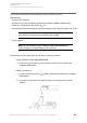
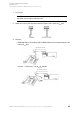
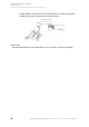
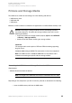
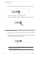
Table Of Contents
- Installation, Operation and Configuration Instructions
- Table of Contents
- Important Information
- Installing and Switching on the PBX
- Preparation
- Network Provider
- Analog End Devices
- ISDN End Devices
- Connecting ISDN End Devices Directly to the Internal S0 Port
- Available Bus Variants for the Installation of an Internal S0 Bus
- Connecting the Cable and the Wall Sockets to the Internal S0 Port (Internal S0 Bus)
- Connecting ISDN End Devices Directly to the internal UP0 Port
- Connecting the Cable and the Wall Sockets to the Internal UP0 Port
- VoIP End Devices
- Printers and Storage Media
- Commissioning
- Using the Configuration Manager
- Configuration Manager
- Minimum Requirements for the PC for Using the Configuration Manager
- Opening the Configuration Manager
- Operating Instructions for the Configuration Manager
- Selecting the Language
- Configuring the Portal Page
- Switching Between Standard and Expert Views
- Using the Configuration Wizard
- Configuring the Port on the Web Server
- Configuring the Maximum Number of Simultaneously Logged-in Users
- Configuring the Time Lapse for Forced Logout
- Help
- Configuration Manager
- Telephoning
- Incoming Calls
- Call Waiting Calls
- Outgoing Calls
- Options for Outgoing Calls
- Initiating an Internal Call
- Initiating an External Call
- Initiating External Calls with Number Presentation Suppression
- Dialling a Telephone Number on Direct Exchange Line Access
- Options for Unsuccessful Calls
- Initiating Internal Callback on Busy
- Initiating External Callback on Busy
- Deleting Callback on Busy
- Initiating Reservation of Exchange Line on Busy
- Initiating Internal Callback on No Response
- Initiating External Callback on No Response
- Initiating Priority Call for Do-Not-Disturb
- Terminating a Query Call
- Query Calls
- Transfer
- Conference Calls
- Managing the Telephone Book and Lists
- Telephone Book
- Call Data
- Contents of the Call Data Set
- Opening the Call Data List
- Columns on the Call Data List
- Exporting the Call Data List
- Deleting Call Data
- Dialling from the Call Data List (Soft Call)
- Configuring the Display
- Switching Automatic Memory Overwriting On/Off
- Switching the Special Dial Tone On/Off when Call Data Memory Full
- Configuring Calls to be Recorded for the Call Data List
- Switching Partial Telephone Number Privacy for Private Calls On/Off
- Configuring a Currency Name
- Configuring the Cost per Call Unit
- Configuring the Billing Factor
- Switching Charge Information On/Off
- Deleting the List of Single Call Records
- Switching Authorization for Deleting Single Call Records On/Off
- Managing Voice Mailboxes and Fax Boxes
- Memory Management for the Voice Mail and Fax Function
- Voice Mailbox
- Configuring a Voice Mailbox
- Creating a Voice Mailbox
- Switching a Voice Mailbox On/Off
- Selecting an Announcement for the Voice Mailbox
- Recording, Saving, Listening to and Deleting an Announcement for Voice Mailboxes
- Recording an Announcement for Voice Mailboxes via an Internal Telephone
- Saving an Announcement for Voice Mailboxes from the PC into the PBX via the Configuration Manager
- Saving the Announcement for Voice Mailboxes on the PC via the Configuration Manager
- Listening to the Announcement for the Voice Mailboxes via the Configuration Manager
- Listening to an Announcement for Voice Mailboxes via an Internal Telephone
- Deleting the Announcement for Voice Mailboxes (Restore Default Announcement) via the Configuration Manager
- Deleting the Announcement for Voice Mailboxes (Restore Default Announcement) via an Internal Telephone
- Switching Message Recording On/Off
- Configuring the Maximum Recording Time per Call
- Configuring the Maximum Recording Time for One Voice Mailbox
- Configuring the Maximum Recording Time for All Voice Mailboxes
- Switching Automatic Cleanup for a Voice Mailbox On/Off
- Querying the Voice Mailbox
- Executing Remote Access
- Configuring the PIN for Remote Access
- Switching the Info Call On/Off
- Importing Language Files
- Fax Box
- RSS Feed
- Configuring and Operating Functions
- Baby Call
- Boss/Secretary Function
- Busy on Busy
- Call Deblocker (Incoming) – VIP Numbers
- Call Deblocker (Outgoing) – Release Codes
- Call Forwarding
- Call Forwarding for External Numbers
- Kinds of Call Forwarding
- Switching Call Forwarding for External Numbers On/Off
- Switching Call Forwarding for External Numbers On/Off via the Configuration Manager
- Switching Call Forwarding Unconditional for External Numbers On/Off via an Internal Telephone
- Switching Call Forwarding on Busy for External Numbers On/Off via an Internal Telephone
- Switching Call Forwarding on No Reply for External Numbers On/Off via an Internal Telephone
- Switching Authorization for Configuring Features on the Exchange Line On/Off
- Configuring the Use of the Feature via the PBX or the Network Provider
- Switching the Use of Any Available Call Channels On/Off
- Configuring the Delay Time for Call Forwarding for External Numbers on No Reply
- Overview of Call Forwarding for External Numbers
- Call Parking
- Call Restrictor (Incoming) – Robinson Numbers
- Call Restrictor (outgoing) – Restricted Numbers
- Call Through
- Call Waiting
- CLIP Texts
- Configuration Switchover
- Configuration-dependent Functions
- Carrying out a Configuration Switchover Manually
- Switching Authorization for Configuration Switching On/Off
- Creating Configurations
- Copying Configurations
- Switching Automatic Configuration Switchover On/Off
- Creating Switching Times for Switching the Configuration
- Copying Switching Times
- Overview of the Configured Switching Times
- Do-not-disturb
- Energy Savings Function (Economy Mode)
- Exchange Line Authorization
- Exchange Line Transfer
- InterCom Announcement/Handsfree
- LAN-TAPI
- LCR
- LCR Sequence
- Configuring LCR
- Switching LCR on the External Connection On/Off
- Configuring Subscribers for LCR
- Importing the LCR Configuration (Providers, Tariff Groups and Data)
- Creating Providers
- Creating Default Networks Based on a Provider Area Code
- Creating Networks Manually
- Creating Prefixes for Networks Manually
- Creating Tariff Information for Networks
- Reading the LCR Configuration from the PBX
- Multi-path Call Forwarding
- Music on Hold and Announcement
- Configuring Music on Hold or Restoring Default Music on Hold
- Saving the Music on Hold from the PC into the PBX via the Configuration Manager
- Saving Music on Hold on the PC via the Configuration Manager
- Setting the Volume of Music on Hold via the Configuration Manager
- Setting the Volume of Music on Hold during the Announcement via the Configuration Manager
- Deleting Music on Hold (Restoring Default Music on Hold) via an Internal Telephone
- Recording and Configuring the Announcement for Music on Hold
- Saving the Announcement for Music on Hold from the PC into the PBX via the Configuration Manager
- Recording an Announcement for Music on Hold via an Internal Telephone
- Saving the Announcement for Music on Hold on the PC via the Configuration Manager
- Setting the Volume of the Announcement for Music on Hold via the Configuration Manager
- Delete the Announcement for Music on Hold (Restore Default Announcement) via an Internal Telephone
- Listening to and Switching the Announcement for Music on Hold On/Off
- Configuring a Pause between Announcements
- Switching Music on Hold in the Call Phase On/Off
- Configuring Music on Hold or Restoring Default Music on Hold
- Network Memory
- Network Printer
- Number Presentation
- Online Name Search
- Pickup
- Private (Personalized) Exchange Line Access
- Room Monitoring
- Short-code Authorization
- Soft Call
- Targeted Exchange Line Access
- Targeted VoIP Access Point
- Telephone Number Display (CLIP)
- Time and Call Allowance Account
- Configuring an Account Type
- Configuring Credit for a Time Account
- Configuring Maximum Credit for Time Accounts
- Configuring Credit for a Call Allowance Account
- Configuring Maximum Credit for Call Allowance Accounts
- Configuring the Type of Call Used for Account Debiting
- Switching Recording Changes for Account Debit during Transfers On/Off
- VoIP/GSM Routing
- Wake-up Functions
- Switching Wake-up On/Off
- Entering a Wake-up Time and Enabling a Wake-up via Configuration Manager
- Switching Wake-up Off via the Configuration Manager
- Entering and Enabling a Wake-up Time via the Internal Telephone
- Switching Wake-up Off via the Internal Telephone
- Deleting the Wake-up Times of all Subscribers via an Internal Telephone
- Overview of the Wake-up Times
- Switching Wake-up on Holidays On/Off
- Configuring the Maximum Number of Wake-up Calls
- Configuring the Call Duration of a Wake-up Call
- Configuring a Pause between Wake-up Calls
- Switching the Recording of Wake-up Calls in the Call Data Base On/Off
- Recording, Saving and Listening to Wake-up Announcements
- Saving the Wake-up Announcement from the PC into the PBX via the Configuration Manager
- Recording a Wake-up Announcement via an Internal Telephone
- Saving the Wake-up Announcement on the PC via the Configuration Manager
- Setting the Volume of Wake-up Announcement via the Configuration Manager
- Listening to a Wake-up Announcement via an Internal Telephone
- Deleting a Wake-up Announcement (Restoring Default Wake-up Announcement) via an Internal Telephone
- Creating Switching Times for Switching the Wake-up Announcement
- Switching Wake-up On/Off
- X.31
- Configuring and Managing the PBX
- Identification
- Internet Access
- Internal Telephone Numbers
- Possible Types of Internal Telephone Numbers
- More Information about the Internal Telephone Number Plan
- Creating Analog Subscribers
- Creating ISDN Subscribers
- Creating VoIP Subscribers
- Creating Notes for Internal Subscribers
- Overview of the Subscribers
- Creating Line Groups
- Assigning Subscribers to a Line Group
- Group Overview
- Overview of Internal Telephone Numbers
- Analog Connection
- Entering the Name for the Analog Connection
- Entering Telephone Numbers
- Overview of External Telephone Numbers
- More Information on Country-specific Settings
- Applying Country-specific Default Settings
- Configuring Flash Time
- Configuring Line Impedance
- Configuring the Reception Amplification
- Configuring Transmission Amplification
- Switching Waiting for Dial Tone for a Line Connection On/Off
- Configuring the Waiting Time for the Line Connection
- Switching Line Access Code Transmission On/Off
- Switching Line Access Code Detection On/Off
- Switching Loop Current Detection for Line Connection On/Off
- Configuring Delay Time after Last Digit Dialled
- Switching Pound Sign Transmission On/Off
- Switching Busy Tone Detection for Call Start On/Off
- Switching Line Polarity Reversal Detection for Start of Call On/Off
- Configuring Maximum Hold Time before Establishing Audio Connection
- Switching Busy Tone Detection (Incoming) for End of Call On/Off
- Switching Busy Tone Detection (Outgoing) for End of Call On/Off
- Switching Continuous Tone Detection at End of Call On/Off
- Switching Loop Current Detection at End of Call On/Off
- Switching DTMF Code Detection at End of Call On/Off
- Switching Line Polarity Reversal Detection for End of Call On/Off
- Configuring the Type of CLIP Information
- Configuring the CLIP Sub-version
- Configuring CLIP Amplification
- Configuring Control Commands
- Configuring Tones
- Configuring the Ringer Frequency
- ISDN Connection
- Configuring the Connection Type for the ISDN Connection
- Switching S0 Bus Monitoring On/Off
- Entering the Name for the ISDN Connection
- Entering Telephone Numbers for the ISDN Point-to-Multipoint Connection
- Entering Telephone Numbers for the ISDN Point-to-Point Connection
- Overview of External Telephone Numbers
- VoIP
- Configuring VoIP Channel Use
- Sequence of an External Call via VoIP
- Configuring External Internet Telephony
- Configuring Internal IP Telephony
- Configuring External Private Branch Exchanges
- Configuring the STUN Server for Operation as an External Private Branch Exchange
- Internal VoIP Subscriber Status Overview
- Switching DiffServ On/Off
- VoIP Provider
- Restoring Default Providers
- Importing VoIP Providers
- Creating a VoIP provider
- Switching Sub-system Operation On/Off
- Configuring a Domain
- Configuring the Registrar
- Configuring Registration Time
- Configuring NAT Traversal and the STUN Server
- Configuring the Outbound Proxy
- Configuring the Interval for NAT Keep Alive
- Configuring the SIP Transport Protocol
- Configuring the SIP Port
- Configuring the SIP Session Timer
- Switching En-bloc Dialling On/Off
- Configuring the Jitter Buffer Value
- Switching Echo Cancellation On/Off
- Switching T.38 for Fax over IP On/Off
- Configuring Codecs
- Configuring the Number Presentation (Outgoing)
- Configuring the Conversion of Incoming VoIP Telephone Numbers
- Exporting VoIP Providers
- Deleting VoIP Providers
- VoIP Account
- Creating a VoIP Account
- Switching VoIP Account Usage On/Off
- Configuring the Exchange Line Access Number (Account Number)
- Configuring a User Name and Password
- Configuring the Authorization ID
- Configuring the Connection Type for the VoIP Account
- Entering Telephone Numbers for the VoIP Point-to-Multipoint Connection
- Entering Telephone Numbers for the VoIP Point-to-Point Connection
- External Telephone Number Overview
- Deleting a VoIP Account
- VoIP Account Status Overview
- DECT System Telephones
- Switching the Log-in Mode over the Base Station On via the Configuration Manager
- Assigning Internal Telephone Numbers to Mobile Handsets
- Logging Mobile Handsets Off via the Configuration Manager
- Configuring the Function Key for PBX Functions via the Configuration Manager
- Copying a Function Key Assignment into Other Mobile Handsets
- Transferring Telephone Numbers from the PBX Telephone Book into the Telephone Book on a DECT System Telephone
- Copying a Telephone Book Selection into Other Mobile Handsets
- GSM Gateway
- Call Distribution
- Call Distribution Groups
- Creating Call Distribution
- Creating Call Distribution via the Configuration Manager
- Creating Call Distribution on the Analog Connection via the Internal Telephones
- Creating Call Distribution on the Point-to-Multipoint Connection via the Internal Telephones
- Deleting Internal Telephone Call Distribution on the ISDN-Point-to-Multipoint Connection
- Configuring the Fax Switch
- Overview of the Call Distribution
- Emergency Call
- PBX Time
- Calendar
- Tones
- Ringer Rhythms
- Ringer Rhythm Display
- Call Differentiation via Ringer Rhythms
- Configuring a Ringer Rhythm for Internal Calls
- Configuring a Ringer Rhythm for External Calls via the Analog Connection
- Configuring a Ringer Rhythm for External Calls via the Point-to-Multipoint Connection
- Configuring a Ringer Rhythm for External Calls via the Point-to-Point Connection
- Configuring the Ringer Frequency
- Protection from Unauthorized Access
- Exchange Line Access
- Transfer and Callback
- PBX Data
- Service and Maintenance
- Status Displays
- Restart
- Firmware Update
- Backing Up and Recovering Configuration Data
- Variants for Backing Up and Recovering Configuration Data
- Saving Configuration Data from the PC/Data Storage Medium in the PBX
- Saving Configuration Data for Automatically Loading onto a Data Storage Medium
- Saving Configuration Data for Automatically Loading from the Data Storage Medium in the PBX
- Saving Configuration Data on the PC
- Inserting a Restoration Point for Configuration Data
- Restoring Configuration Data from a Restoration Point
- Resetting the Configuration
- Remote Configuration and Alternative Connection Options
- Possible Connection Options for Configuring the PBX and the Connected ISDN System Telephones
- Configuring the PBX Remotely via the Internet (Externally)
- Configuring the PBX via an Internal S0 Port (PPP Internal)
- Configuring the PBX Remotely via an External S0 Port (PPP External)
- Configuring ISDN System Telephones via the PBX (Internal)
- Configuring ISDN System Telephones Remotely via the External S0 Port on the PBX (Externally)
- Configuring Local and Remote IP Addresses
- Configuring the External PIN
- Configuring the Remote Switching Number
- Configuring the Remote Switching Number for System Telephones
- Configuring the Configuration Port for System Telephones
- Configuring Internal CAPI Dial-in Numbers
- Configuring Dealer Access Numbers
- Configuring a Dial-up Connection on the PC
- Release the PBX for Remote Configuration
- Factory Settings
- Powering Down
- Ejecting a Storage Medium
- Expanding the PBX
- Service Data
- Short Operation Instructions
- Glossary
- Terminology and Functions
- A
- B
- C
- Call Data
- Call Deblocker (Incoming) – VIP Numbers
- Call Deblocker (Outgoing) – Release Codes
- Call Forwarding
- Call Parking
- Call Restrictor (Incoming) – Robinson Numbers
- Call Restrictor (outgoing) – Restricted Numbers
- Call Take-over
- Call Through
- Call Waiting
- Callback on Busy
- Callback on No Reply
- Central Office
- CNG
- Codec
- Conference Calls
- Configuration Manager
- Configuration Switchover
- Cross-Site Scripting (XSS)
- D
- E
- F
- G
- H
- I
- J
- L
- M
- N
- O
- P
- Q
- R
- S
- T
- U
- V
- W
- X
- Abbreviations
- Terminology and Functions
- Index

COMpact 3000 analog/ISDN/VoIP - Firmware Version 4.0 - Version of the Manual 03 02/11 61
Installing and Switching on the PBX
ISDN End Devices
Connecting the Cable and the Wall Sockets to the Internal S
0
Port (Internal S
0
Bus)
Connecting the Cable and the Wall Sockets to the Internal S
0
Port (Internal S
0
Bus)
Requirements:
– Cover panel is removed
– Internal S
0
port (only provided at the optionally available COMpact S
0
module or COMpact
ISDN module)
– Terminators enabled or disabled at the internal S
0
port, depending on the bus variant
– Compliance with the maximum distance/line length between the devices, depending on the
bus variant
– 4-core installation cable (e. g. J-Y(St)Y 2x2x0,6), preferably star quad stranding
– Under unfavorable conditions, for example, near a strong transmitter or an electrical power
line: screened cable
– ISDN wall sockets (e. g. IAE or UAE8)
Note: If possible, only use wall sockets of one type.
– Two terminators (100 Ohm; load capacity min. 0.25 W) for any wall socket at the end position
1. Lay the lines according to the selected bus variant.
2. Attach the wires to the four terminal clamps at the internal S
0
port.
Note:
When assigning the individual wires, orient yourself with the identifiers
subsequently listed or refer to VDE 0815 when identifiers deviate.
Warning: Power surges, which can occur during electrical storms, can
cause life-threatening electric shocks or damage/destroy the PBX.
• Lay all the cables inside the building.
• Do not use the S
0
ports for connecting an external private branch
exchange.
Cable with Two
Twin Wires
Cable with Star Quad
Physical circuit/
pair 1
a1
b1
red
black
without ring
single rings, 17 mm spacing
Physical circuit/
pair 2
a2
b2
white
yellow
double rings, 34 mm spacing
double rings, 17 mm spacing