
Technical data
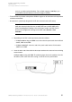
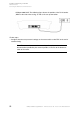
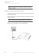
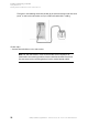
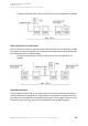
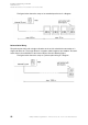
Table Of Contents
- Installation, Operation and Configuration Instructions
- Table of Contents
- Important Information
- Installing and Switching on the PBX
- Preparation
- Network Provider
- Analog End Devices
- ISDN End Devices
- Connecting ISDN End Devices Directly to the Internal S0 Port
- Available Bus Variants for the Installation of an Internal S0 Bus
- Connecting the Cable and the Wall Sockets to the Internal S0 Port (Internal S0 Bus)
- Connecting ISDN End Devices Directly to the internal UP0 Port
- Connecting the Cable and the Wall Sockets to the Internal UP0 Port
- VoIP End Devices
- Printers and Storage Media
- Commissioning
- Using the Configuration Manager
- Configuration Manager
- Minimum Requirements for the PC for Using the Configuration Manager
- Opening the Configuration Manager
- Operating Instructions for the Configuration Manager
- Selecting the Language
- Configuring the Portal Page
- Switching Between Standard and Expert Views
- Using the Configuration Wizard
- Configuring the Port on the Web Server
- Configuring the Maximum Number of Simultaneously Logged-in Users
- Configuring the Time Lapse for Forced Logout
- Help
- Configuration Manager
- Telephoning
- Incoming Calls
- Call Waiting Calls
- Outgoing Calls
- Options for Outgoing Calls
- Initiating an Internal Call
- Initiating an External Call
- Initiating External Calls with Number Presentation Suppression
- Dialling a Telephone Number on Direct Exchange Line Access
- Options for Unsuccessful Calls
- Initiating Internal Callback on Busy
- Initiating External Callback on Busy
- Deleting Callback on Busy
- Initiating Reservation of Exchange Line on Busy
- Initiating Internal Callback on No Response
- Initiating External Callback on No Response
- Initiating Priority Call for Do-Not-Disturb
- Terminating a Query Call
- Query Calls
- Transfer
- Conference Calls
- Managing the Telephone Book and Lists
- Telephone Book
- Call Data
- Contents of the Call Data Set
- Opening the Call Data List
- Columns on the Call Data List
- Exporting the Call Data List
- Deleting Call Data
- Dialling from the Call Data List (Soft Call)
- Configuring the Display
- Switching Automatic Memory Overwriting On/Off
- Switching the Special Dial Tone On/Off when Call Data Memory Full
- Configuring Calls to be Recorded for the Call Data List
- Switching Partial Telephone Number Privacy for Private Calls On/Off
- Configuring a Currency Name
- Configuring the Cost per Call Unit
- Configuring the Billing Factor
- Switching Charge Information On/Off
- Deleting the List of Single Call Records
- Switching Authorization for Deleting Single Call Records On/Off
- Managing Voice Mailboxes and Fax Boxes
- Memory Management for the Voice Mail and Fax Function
- Voice Mailbox
- Configuring a Voice Mailbox
- Creating a Voice Mailbox
- Switching a Voice Mailbox On/Off
- Selecting an Announcement for the Voice Mailbox
- Recording, Saving, Listening to and Deleting an Announcement for Voice Mailboxes
- Recording an Announcement for Voice Mailboxes via an Internal Telephone
- Saving an Announcement for Voice Mailboxes from the PC into the PBX via the Configuration Manager
- Saving the Announcement for Voice Mailboxes on the PC via the Configuration Manager
- Listening to the Announcement for the Voice Mailboxes via the Configuration Manager
- Listening to an Announcement for Voice Mailboxes via an Internal Telephone
- Deleting the Announcement for Voice Mailboxes (Restore Default Announcement) via the Configuration Manager
- Deleting the Announcement for Voice Mailboxes (Restore Default Announcement) via an Internal Telephone
- Switching Message Recording On/Off
- Configuring the Maximum Recording Time per Call
- Configuring the Maximum Recording Time for One Voice Mailbox
- Configuring the Maximum Recording Time for All Voice Mailboxes
- Switching Automatic Cleanup for a Voice Mailbox On/Off
- Querying the Voice Mailbox
- Executing Remote Access
- Configuring the PIN for Remote Access
- Switching the Info Call On/Off
- Importing Language Files
- Fax Box
- RSS Feed
- Configuring and Operating Functions
- Baby Call
- Boss/Secretary Function
- Busy on Busy
- Call Deblocker (Incoming) – VIP Numbers
- Call Deblocker (Outgoing) – Release Codes
- Call Forwarding
- Call Forwarding for External Numbers
- Kinds of Call Forwarding
- Switching Call Forwarding for External Numbers On/Off
- Switching Call Forwarding for External Numbers On/Off via the Configuration Manager
- Switching Call Forwarding Unconditional for External Numbers On/Off via an Internal Telephone
- Switching Call Forwarding on Busy for External Numbers On/Off via an Internal Telephone
- Switching Call Forwarding on No Reply for External Numbers On/Off via an Internal Telephone
- Switching Authorization for Configuring Features on the Exchange Line On/Off
- Configuring the Use of the Feature via the PBX or the Network Provider
- Switching the Use of Any Available Call Channels On/Off
- Configuring the Delay Time for Call Forwarding for External Numbers on No Reply
- Overview of Call Forwarding for External Numbers
- Call Parking
- Call Restrictor (Incoming) – Robinson Numbers
- Call Restrictor (outgoing) – Restricted Numbers
- Call Through
- Call Waiting
- CLIP Texts
- Configuration Switchover
- Configuration-dependent Functions
- Carrying out a Configuration Switchover Manually
- Switching Authorization for Configuration Switching On/Off
- Creating Configurations
- Copying Configurations
- Switching Automatic Configuration Switchover On/Off
- Creating Switching Times for Switching the Configuration
- Copying Switching Times
- Overview of the Configured Switching Times
- Do-not-disturb
- Energy Savings Function (Economy Mode)
- Exchange Line Authorization
- Exchange Line Transfer
- InterCom Announcement/Handsfree
- LAN-TAPI
- LCR
- LCR Sequence
- Configuring LCR
- Switching LCR on the External Connection On/Off
- Configuring Subscribers for LCR
- Importing the LCR Configuration (Providers, Tariff Groups and Data)
- Creating Providers
- Creating Default Networks Based on a Provider Area Code
- Creating Networks Manually
- Creating Prefixes for Networks Manually
- Creating Tariff Information for Networks
- Reading the LCR Configuration from the PBX
- Multi-path Call Forwarding
- Music on Hold and Announcement
- Configuring Music on Hold or Restoring Default Music on Hold
- Saving the Music on Hold from the PC into the PBX via the Configuration Manager
- Saving Music on Hold on the PC via the Configuration Manager
- Setting the Volume of Music on Hold via the Configuration Manager
- Setting the Volume of Music on Hold during the Announcement via the Configuration Manager
- Deleting Music on Hold (Restoring Default Music on Hold) via an Internal Telephone
- Recording and Configuring the Announcement for Music on Hold
- Saving the Announcement for Music on Hold from the PC into the PBX via the Configuration Manager
- Recording an Announcement for Music on Hold via an Internal Telephone
- Saving the Announcement for Music on Hold on the PC via the Configuration Manager
- Setting the Volume of the Announcement for Music on Hold via the Configuration Manager
- Delete the Announcement for Music on Hold (Restore Default Announcement) via an Internal Telephone
- Listening to and Switching the Announcement for Music on Hold On/Off
- Configuring a Pause between Announcements
- Switching Music on Hold in the Call Phase On/Off
- Configuring Music on Hold or Restoring Default Music on Hold
- Network Memory
- Network Printer
- Number Presentation
- Online Name Search
- Pickup
- Private (Personalized) Exchange Line Access
- Room Monitoring
- Short-code Authorization
- Soft Call
- Targeted Exchange Line Access
- Targeted VoIP Access Point
- Telephone Number Display (CLIP)
- Time and Call Allowance Account
- Configuring an Account Type
- Configuring Credit for a Time Account
- Configuring Maximum Credit for Time Accounts
- Configuring Credit for a Call Allowance Account
- Configuring Maximum Credit for Call Allowance Accounts
- Configuring the Type of Call Used for Account Debiting
- Switching Recording Changes for Account Debit during Transfers On/Off
- VoIP/GSM Routing
- Wake-up Functions
- Switching Wake-up On/Off
- Entering a Wake-up Time and Enabling a Wake-up via Configuration Manager
- Switching Wake-up Off via the Configuration Manager
- Entering and Enabling a Wake-up Time via the Internal Telephone
- Switching Wake-up Off via the Internal Telephone
- Deleting the Wake-up Times of all Subscribers via an Internal Telephone
- Overview of the Wake-up Times
- Switching Wake-up on Holidays On/Off
- Configuring the Maximum Number of Wake-up Calls
- Configuring the Call Duration of a Wake-up Call
- Configuring a Pause between Wake-up Calls
- Switching the Recording of Wake-up Calls in the Call Data Base On/Off
- Recording, Saving and Listening to Wake-up Announcements
- Saving the Wake-up Announcement from the PC into the PBX via the Configuration Manager
- Recording a Wake-up Announcement via an Internal Telephone
- Saving the Wake-up Announcement on the PC via the Configuration Manager
- Setting the Volume of Wake-up Announcement via the Configuration Manager
- Listening to a Wake-up Announcement via an Internal Telephone
- Deleting a Wake-up Announcement (Restoring Default Wake-up Announcement) via an Internal Telephone
- Creating Switching Times for Switching the Wake-up Announcement
- Switching Wake-up On/Off
- X.31
- Configuring and Managing the PBX
- Identification
- Internet Access
- Internal Telephone Numbers
- Possible Types of Internal Telephone Numbers
- More Information about the Internal Telephone Number Plan
- Creating Analog Subscribers
- Creating ISDN Subscribers
- Creating VoIP Subscribers
- Creating Notes for Internal Subscribers
- Overview of the Subscribers
- Creating Line Groups
- Assigning Subscribers to a Line Group
- Group Overview
- Overview of Internal Telephone Numbers
- Analog Connection
- Entering the Name for the Analog Connection
- Entering Telephone Numbers
- Overview of External Telephone Numbers
- More Information on Country-specific Settings
- Applying Country-specific Default Settings
- Configuring Flash Time
- Configuring Line Impedance
- Configuring the Reception Amplification
- Configuring Transmission Amplification
- Switching Waiting for Dial Tone for a Line Connection On/Off
- Configuring the Waiting Time for the Line Connection
- Switching Line Access Code Transmission On/Off
- Switching Line Access Code Detection On/Off
- Switching Loop Current Detection for Line Connection On/Off
- Configuring Delay Time after Last Digit Dialled
- Switching Pound Sign Transmission On/Off
- Switching Busy Tone Detection for Call Start On/Off
- Switching Line Polarity Reversal Detection for Start of Call On/Off
- Configuring Maximum Hold Time before Establishing Audio Connection
- Switching Busy Tone Detection (Incoming) for End of Call On/Off
- Switching Busy Tone Detection (Outgoing) for End of Call On/Off
- Switching Continuous Tone Detection at End of Call On/Off
- Switching Loop Current Detection at End of Call On/Off
- Switching DTMF Code Detection at End of Call On/Off
- Switching Line Polarity Reversal Detection for End of Call On/Off
- Configuring the Type of CLIP Information
- Configuring the CLIP Sub-version
- Configuring CLIP Amplification
- Configuring Control Commands
- Configuring Tones
- Configuring the Ringer Frequency
- ISDN Connection
- Configuring the Connection Type for the ISDN Connection
- Switching S0 Bus Monitoring On/Off
- Entering the Name for the ISDN Connection
- Entering Telephone Numbers for the ISDN Point-to-Multipoint Connection
- Entering Telephone Numbers for the ISDN Point-to-Point Connection
- Overview of External Telephone Numbers
- VoIP
- Configuring VoIP Channel Use
- Sequence of an External Call via VoIP
- Configuring External Internet Telephony
- Configuring Internal IP Telephony
- Configuring External Private Branch Exchanges
- Configuring the STUN Server for Operation as an External Private Branch Exchange
- Internal VoIP Subscriber Status Overview
- Switching DiffServ On/Off
- VoIP Provider
- Restoring Default Providers
- Importing VoIP Providers
- Creating a VoIP provider
- Switching Sub-system Operation On/Off
- Configuring a Domain
- Configuring the Registrar
- Configuring Registration Time
- Configuring NAT Traversal and the STUN Server
- Configuring the Outbound Proxy
- Configuring the Interval for NAT Keep Alive
- Configuring the SIP Transport Protocol
- Configuring the SIP Port
- Configuring the SIP Session Timer
- Switching En-bloc Dialling On/Off
- Configuring the Jitter Buffer Value
- Switching Echo Cancellation On/Off
- Switching T.38 for Fax over IP On/Off
- Configuring Codecs
- Configuring the Number Presentation (Outgoing)
- Configuring the Conversion of Incoming VoIP Telephone Numbers
- Exporting VoIP Providers
- Deleting VoIP Providers
- VoIP Account
- Creating a VoIP Account
- Switching VoIP Account Usage On/Off
- Configuring the Exchange Line Access Number (Account Number)
- Configuring a User Name and Password
- Configuring the Authorization ID
- Configuring the Connection Type for the VoIP Account
- Entering Telephone Numbers for the VoIP Point-to-Multipoint Connection
- Entering Telephone Numbers for the VoIP Point-to-Point Connection
- External Telephone Number Overview
- Deleting a VoIP Account
- VoIP Account Status Overview
- DECT System Telephones
- Switching the Log-in Mode over the Base Station On via the Configuration Manager
- Assigning Internal Telephone Numbers to Mobile Handsets
- Logging Mobile Handsets Off via the Configuration Manager
- Configuring the Function Key for PBX Functions via the Configuration Manager
- Copying a Function Key Assignment into Other Mobile Handsets
- Transferring Telephone Numbers from the PBX Telephone Book into the Telephone Book on a DECT System Telephone
- Copying a Telephone Book Selection into Other Mobile Handsets
- GSM Gateway
- Call Distribution
- Call Distribution Groups
- Creating Call Distribution
- Creating Call Distribution via the Configuration Manager
- Creating Call Distribution on the Analog Connection via the Internal Telephones
- Creating Call Distribution on the Point-to-Multipoint Connection via the Internal Telephones
- Deleting Internal Telephone Call Distribution on the ISDN-Point-to-Multipoint Connection
- Configuring the Fax Switch
- Overview of the Call Distribution
- Emergency Call
- PBX Time
- Calendar
- Tones
- Ringer Rhythms
- Ringer Rhythm Display
- Call Differentiation via Ringer Rhythms
- Configuring a Ringer Rhythm for Internal Calls
- Configuring a Ringer Rhythm for External Calls via the Analog Connection
- Configuring a Ringer Rhythm for External Calls via the Point-to-Multipoint Connection
- Configuring a Ringer Rhythm for External Calls via the Point-to-Point Connection
- Configuring the Ringer Frequency
- Protection from Unauthorized Access
- Exchange Line Access
- Transfer and Callback
- PBX Data
- Service and Maintenance
- Status Displays
- Restart
- Firmware Update
- Backing Up and Recovering Configuration Data
- Variants for Backing Up and Recovering Configuration Data
- Saving Configuration Data from the PC/Data Storage Medium in the PBX
- Saving Configuration Data for Automatically Loading onto a Data Storage Medium
- Saving Configuration Data for Automatically Loading from the Data Storage Medium in the PBX
- Saving Configuration Data on the PC
- Inserting a Restoration Point for Configuration Data
- Restoring Configuration Data from a Restoration Point
- Resetting the Configuration
- Remote Configuration and Alternative Connection Options
- Possible Connection Options for Configuring the PBX and the Connected ISDN System Telephones
- Configuring the PBX Remotely via the Internet (Externally)
- Configuring the PBX via an Internal S0 Port (PPP Internal)
- Configuring the PBX Remotely via an External S0 Port (PPP External)
- Configuring ISDN System Telephones via the PBX (Internal)
- Configuring ISDN System Telephones Remotely via the External S0 Port on the PBX (Externally)
- Configuring Local and Remote IP Addresses
- Configuring the External PIN
- Configuring the Remote Switching Number
- Configuring the Remote Switching Number for System Telephones
- Configuring the Configuration Port for System Telephones
- Configuring Internal CAPI Dial-in Numbers
- Configuring Dealer Access Numbers
- Configuring a Dial-up Connection on the PC
- Release the PBX for Remote Configuration
- Factory Settings
- Powering Down
- Ejecting a Storage Medium
- Expanding the PBX
- Service Data
- Short Operation Instructions
- Glossary
- Terminology and Functions
- A
- B
- C
- Call Data
- Call Deblocker (Incoming) – VIP Numbers
- Call Deblocker (Outgoing) – Release Codes
- Call Forwarding
- Call Parking
- Call Restrictor (Incoming) – Robinson Numbers
- Call Restrictor (outgoing) – Restricted Numbers
- Call Take-over
- Call Through
- Call Waiting
- Callback on Busy
- Callback on No Reply
- Central Office
- CNG
- Codec
- Conference Calls
- Configuration Manager
- Configuration Switchover
- Cross-Site Scripting (XSS)
- D
- E
- F
- G
- H
- I
- J
- L
- M
- N
- O
- P
- Q
- R
- S
- T
- U
- V
- W
- X
- Abbreviations
- Terminology and Functions
- Index

COMpact 3000 analog/ISDN/VoIP - Firmware Version 4.0 - Version of the Manual 03 02/11 55
Installing and Switching on the PBX
Analog End Devices
Installing Cables and Wall Sockets at the Internal a/b Port
Installing Cables and Wall Sockets at the Internal a/b Port
Requirements:
– Cover panel is removed
– Keeping the maximal distance/line length between the devices depending of the cable used
(with a pair diameter of 0.6 mm: approximately 790 m )
– Per a/b port, one wire pair of an installation cable (e. g. J-Y(St)Y 2x2x0,6)
– Under unfavorable conditions, for example, near a strong transmitter or an electrical power
line: screened cable
– For telephones or combination fax/answering machines: a TAE wall socket with F coding (a
single socket labeled with an F)
– For fax machines, modems, and call answering machines: a TAE wall socket with an
additional socket with N coding
Note: Outside of Germany, use RJ-45 sockets or the analog wall sockets
normally used in the country in question.
1. Lay the line.
Note: Prevent interferences. Avoid laying long lengths of parallel lines,
especially next to mains. Twist the pairs.
2. Attach the wires to the two terminal clamps at the internal a/b port.
3. Connect the wall sockets to the terminal clamps at the internal a/b port.
Warning: Power surges, which can occur during electrical storms, can
cause life-threatening electric shocks or damage/destroy the PBX.
• Lay all the cables inside the building.
• Do not use the a/b ports to connect external private branch exchanges.