
Service manual


STP 11-25R13-SM-TG
3 - 35
REPAIR A COLOR TELEVISION (TV) CAMERA
113-575-0052
Conditions: In a tactical or garrison environment, given a TV camera submitted for repair on a DA Form
2407, WFM, vectorscope, dual-trace oscilloscope with 10X test probes, multimeter with test leads,
VTSG, sync generator, color TV monitor, dummy load, electronic equipment tool kit, soldering tool kit
(light to medium duty), registration chart, logarithmic chart (gray scale), lens tissue, glass cleaner, bench
stock, system block diagrams, manufacturers' manuals, and DA Pam 738-750. Electronic News
Gathering (ENG) cameras also require interface cables, an attached VTR, fully charged battery pack or
AC adapter, microphone, blank video tapes (10 minutes or longer), and an audio monitor.
Standards: The standards are met when the camera is free of defects and its output signal meets the
National Television Standards Committee (NTSC) standards.
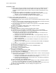
Performance Steps
1. Review DA Form 2407.
2. Sectionalize the trouble to a defective stage.
a. Visually inspect for physical damage, missing controls, broken switches, cracked components,
loose connectors, and other discrepancies.
b. Clean the camera lens (if necessary) with lens tissue and glass cleaner.
c. Operations check the camera to verify that the deficiency or symptom exists and to what extent.
(1) Connect subcarrier reference from the output of the sync generator or VTSG to the
external subcarrier reference of the camera.
(2) Turn ON and set up the sync generator, VTSG, WFM, vectorscope, and video monitor.
(3) Set the camera to STANDBY (operate) mode. Set the BARS-CAMERA selector to BARS
and adjust the CONTRAST and BRIGHTNESS controls on the viewfinder.
(4) Check color phase by using the internal BARS and by monitoring the vectorscope.
(5) Check video (100 IRE) and black (7.5 IRE) levels by using the internal BARS and by
monitoring the WFM.
(6) Check registration.
(7) Check white balance and black balance with the gray scale chart.
(8) Frame an object or scene with the camera by adjusting the zoom and focus controls while
observing the picture in the viewfinder. Adjust the iris (do not exceed 100 IRE) while
observing the WFM. Check the video monitor for signs of video flaring, clipping, or
shading problems.
(9) Check all auto functions (iris, black-white balance, centering, and back focus).
(10) Recognize symptoms.
( a) A dead camera does not work at all (no power).
( b) A weak camera works but lacks usual signal response.
( c) An intermittent symptom comes and goes, or the camera works now and then.
( d) Distortion causes the camera to not quite work properly.
( e) Noise causes interference or hum.
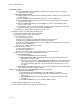
3. Localize the trouble to a specific circuit.
a. Analyze overall block diagrams and schematics.
b. Perform functional tests on suspected circuits.
c. Inject signal through the primary video path to trace and find where the signal was lost or
distorted.
(1) Select a test saw (white window) signal from the VTSG into the pre-amps.
(2) If the output signal is not white, determine which color(s) is missing.
( a) A white signal contains the primary colors (red, green, and blue (RGB).
( b) A cyan signal (blue and green) indicates the loss of the red circuitry.
( c) A magenta signal (red and blue) indicates the loss of the green circuitry.
(3) Remove the test signal.