
Service manual


STP 11-25R13-SM-TG
U - 14
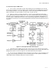
d. K Factor.
(1) The pressure and hence the density of the atmosphere surrounding the earth varies with height,
getting less as the height increases and the weight of air above decreases. As a result, the dielectric
constant also decreases with height and thus has a prismatic effect causing microwaves (and light
waves) to bend towards the earth. Under normal conditions the bending is less than the curvature of the
earth, but nonetheless the microwaves will go further than simple geometry would suggest. A convenient
radius way in which to allow for this is to increase the effective radius of the earth until the microwaves
appear to be traveling in straight lines.
(2) The ratio of the effective to the true earth radius is called K and is approximately 4/3 or 1.33 for
over 90 percent of the time in most parts of the world. However, there are times when K can be anything
from infinity to as low as 0.45. K = infinity (flat earth) is a condition where mirages will be seen and radar
echoes received from hundreds of miles away. It is an embarrassment as interference between systems
is increased; fortunately, it is relatively rare.
(3) K values between 1 and 0.5 can occur for a few percentages of a year and it is necessary to
design a link to take this into account if a reliable system is to be achieved. Within the USA, a map
showing contours of minimum K factor is available and should be consulted before settling on the
necessary antenna heights.
e. Clearance Requirements.
(1) A microwave signal is attenuated when the path is close to an obstruction. Clearance is stated
as a ratio of the first Fresnel zone (FFZ), a function of frequency.
(2) K factor variation will mean that more clearance must be built in, to allow for values less than
4/3, and a typical design parameter is to plan for 0.3 FFZ for the lowest K value expected on the path.
While such a clearance will introduce 2 to 8 dB of loss, this is well within the fade margin of a well-
designed link.
f. Path Profiles.
(1) Sites for microwave link terminals are likely to be studios, earth stations or TV transmitters, all
of which are predetermined. Choice of sites for repeaters, if they are necessary, may be constrained by
availability and access.
(2) To see if any combination of sites is viable, and to determine the antenna heights at each end
of the chosen path, requires the plotting of a profile. The profile, a plot of ground height against distance,
can be drawn on simple squared or special K factor paper (usually K = 4/3). Squared paper has the
advantage that any convenient scales can be used for x and y-axis; 4/3 paper has the advantage that
potential obstructions are more obvious and the effect of path length on necessary clearance stands out.
Whichever paper is used, the next step after plotting the profile is to add an allowance to high points for
trees on buildings. Then the effect of low values of K must be added to any potential obstruction point.
(3) Then a straight line clearing the upper values at each point will pass through the terminals at
the minimum antenna height for adequate clearance. If most obstructions are near one end of the path, it
may be more economic to raise the antenna at that end and save more height at the other end.