
Service manual


STP 11-25R13-SM-TG
U - 13
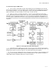
(2) A passive repeater has equal gain receiving and transmitting. Gain here is defined as the ratio
of the power at a given (far-field) point relative to that which would be received at that point if the passive
were replaced by a matched isotropic antenna fed with the same RF power.
U-8. Path Performance.
a. Free Space Path Loss.
(1) Free space path loss for any electromagnetic wave arises from the spreading of the wavefront
radiating from the source, like ripples on a pond after a stone has been thrown in. The loss increases by
6 dB (4:1 in power) every time the range doubles once outside the near field of the antenna. Since a 2:1
increase in range gives 4:1 (2
2
:1) reduction in power, this relationship is sometimes referred to as the
inverse square law.
(2) This loss is expressed between isotropic antennas (a theoretical antenna which radiates equally
in all directions). The gain of a microwave antenna is then expressed in dBi (gain relative to isotropic).
Below about 1000 MHz, it is usual to express gain as dBd (gain relative to a dipole): 0 dBd = 2.2 dBi.
Strictly, the gain is the amount by which the directional properties of the antenna reduce the coupling
loss.
b. Other Sources of Path Loss.
(1) The free space loss is easily calculated; antenna manufacturer’s issue slide rules from which
the loss and antenna gains can be read.
(2) However, atmospheric and other changes will cause the loss to vary from time to time and
these effects should be considered when discussing microwave systems. These changes and effects
are:
(a) Multipath (i.e., signals arriving at the receiving antenna by reflections from water, hills, buildings,
or atmospheric discontinuities as well as by the direct path) can add to or cancel the signal, causing an
increase up to 6 dB or a decrease of more than 50 dB.
(b) Atmospheric bending of the wavefront due to abnormal changes of temperature and/or humidity
with height can cause loss of signal due to diversion from the desired direction. This effect is discussed
later under "K factor".
(c) Rainfall, and to a lesser extent snowfall, can attenuate the signal, an effect that increases
markedly with increasing frequency.
(3) To offset these effects a system is designed to have a more than adequate signal level at the
receiver under free space loss conditions, (which is normal for at least 90 percent of the time). The
excess of signal over the minimum required is called the fade margin. Typical fade margins are in the
range 26 to 46 dB and ideally will be larger for higher frequencies, longer paths and over water or similar
difficult paths.
(4) The choice of fade margins may involve compromises; for example, when existing towers of
masts limit the size of the antenna. The environment, more being desirable in humid, flat country and
less in dry mountainous areas, could also influence it.
c. Outages. Outage time, which is time out of service due to propagation, or availability, equals
100x (1-outage) when the latter is expressed as a fraction of time, and can be calculated from an
accepted formula. This assumes the path has adequate clearance for the area, and is based on
frequency, path length, and two factors related to terrain roughness (the rougher the better as this breaks
up the atmosphere) and humidity (the lower the better as moisture can cause discontinuities). However,
rainfall can be more or less an important factor depending on the area.