
Service manual


STP 11-25R13-SM-TG
U - 11
(3) Grid Antennas. Cannot be used with cross-polarized feeds, as they will only reflect signals that
are polarized in parallel with the grids.
(4) Horns. Several variations of the horn antenna are available for microwave use. They are
characterized by better radiation patterns than parabolic reflectors but their weight and windage requires
heavy towers and their use is limited to severely congested areas.
(5) Omni. The omnidirectional antenna is characterized by a radiation pattern resembling a
doughnut. Gain is achieved by reducing radiation in the vertical direction. They are often used to
eliminate the need for tracking in mobile systems with typical gains of 6 dB on the vehicle or 10 dB at
fixed points. The higher gain antenna is not used on helicopters or motorcycles as the signal loss when
the vehicle banks during turns would be excessive.
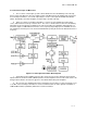
b. Passive Reflectors. Passive reflectors are often used at 7 and 13 GHz instead of feeder
waveguide to affect radiation at the top of the tower. The advantage of passive reflectors is the
elimination of waveguide feeder loss and cost; the disadvantage is stray re-radiation from the tower
structure that limits frequency reuse by degrading the radiation pattern.
(1) The installation consists of a parabola near the equipment aimed at a reflector tilted about 45
degrees with the earth that reflects the energy away from the tower in a horizontal line. The efficiency of
the reflector depends upon how well it is illuminated by the parabola. Curved reflectors are sometimes
used to improve efficiency by 2 dB or so. All installations must meet FCC standards.
(2) Adjustment of reflectors in the field requires skill but is accomplished with the assistance of
surveying equipment for initial adjustment and trial and error for best-received signal after the equipment
is installed. Most popular sizes are 6 by 8, 8 by 10, 8 by 12, and 10 by 15 feet fed by 4-, 6-, 8-, and 10-
foot parabolas. The larger the antenna-reflector spacing, the larger the antenna needed to concentrate
the energy onto the reflector. Over- or under-concentration leads to inefficient illumination of the reflector
and loss of performance.
c. Antenna Feeders. Microwave equipment is connected to the antenna with either coaxial cable
or waveguide. Coaxial is used for 1 and 2 GHz and may be either foam-filled or air dielectric. Waveguide
is used for 7 and 13 GHz and may be either rigid rectangular, elliptical flexible, or circular waveguide.
(1) Flexible Rectangular Waveguide.
(a) Short sections of flexible rectangular waveguide are often used to simplify installation. In
addition to the lines, various hangers, clamps, bending tools, hoisting grips, and pressuring equipment
are required for installation. It is recommended that transmission lines be installed in continuous lengths
to avoid potential problems with splices or joints.
(b) Care must be taken during installation to avoid J pressure leaks, dents, and discontinuities, all
of which will affect the system performance. Typical losses vary from 1 to 14 dB per hundred feet,
depending upon the type of feeder used.
(2) Foam-filled Coaxial Cable. Foam-filled coaxial cable is the easiest line to install but has higher
loss than air dielectric; it must only be used in conjunction with a foam-filled (nonpressurized) antenna.
(3) Maintaining Positive Pressure. When waveguide, or air-filled coaxial cable, is being used it
must be maintained at a positive pressure (0.5 to 5 PSI) above atmospheric with dry air or nitrogen.