
Service manual


STP 11-25R13-SM-TG
U - 10
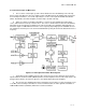
(3) Due to residual nonlinearity in the microwave modulator and demodulator, as well as in the
path, sometimes cross modulation of the video appears on the demodulated audio. The most annoying
characteristic is a 15.7 kHz buzz caused by the video horizontal scanning frequency. Subcarrier
demodulator manufacturers often include a 15.7 kHz notch in their audio-processing circuitry to suppress
this tone. This notch requirement is difficult, as little attenuation at 15 kHz (top of the audio band) is
allowed. In addition, 75 usec de-emphasis and perhaps, noise low-pass filtering above 15 kHz is
included in the audio circuitry.
(4) Audio output level is generally +9 to +18 dBm, at a balanced 600 ohms; for multiple outputs, a
low-impedance option is sometimes available.
U-7. Antenna and Waveguide Considerations.
a. Antenna Systems. Several different types of antennas are used in a TV microwave system.
Omnidirectional vertical and directional horizontal stacked arrays are used for portable and vehicular
applications. Parabolic reflector antennas are used for STL, intercity, ETV, and CARS systems. Comer
reflectors and modified parabolas are sometimes used for 950 MHz STLs. Horn or shrouded parabolic
antennas may be used for high front-to-back isolation ratios. Simple dipoles are often used for backpack
and wireless microphone equipment. Selection of the antenna is usually based upon the application and
the antennas available.
(1) Isotropic. As noted above, the isotropic antenna is a hypothetical antenna used as a reference
against which the gain of other microwave antennas is measured. The term dBi denotes gain over an
isotropic antenna. The isotropic antenna by definition has a radiation pattern that is a perfect sphere. It
is also called unipole.
(2) Parabolas. The parabolic antenna is available with several useful refinements.
(a) Radomes, heated and unheated, are available to prevent icing which rapidly reduces efficiency,
especially at the higher frequencies.
(b) Special shrouds are available to improve the radiation pattern and increase front-to-back gain
ratios.
(c) Dual cross-polarized feeds are available that provide 25 dB or so of isolation between two
signals using the same reflector.
(d) Antennas at 1 and 2 GHz normally use coaxial dipole feeds while those at 7 and 13 GHz
usually use waveguide horn feeds.
(e) Standard mounting structures are available for attaching the antenna to a 4.5-inch (OD) pipe,
along with clamps that can be loosened for aiming the antenna after installation on a tower. Special
lightweight 950 MHz antennas sometimes mount to a 2-inch (OD) pipe.
(f) Special roof mounts are available for aiming the antenna upward when passive reflectors are
used on the tower.
(g) Feeders must be airtight so that pressurized moisture will not enter and reduce feed efficiency.
(h) At the lower frequencies, grid and mesh construction is often used to reduce weight and wind
loading on the towers.