
Service manual


STP 11-25R13-SM-TG
U - 8
U-5. Power Supplies.
a. Whether remodulating or heterodyne, microwave equipment uses several different voltages to
power the various active circuit components. These are usually low voltages in the 12 to 35 ranges that
must be highly regulated and filtered for best performance. The power supply function is to convert the
AC or DC main supply voltage to those required in the equipment.
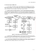
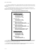
b. Figure U-4 shows a typical power supply system. AC units consist of a transformer and
rectifiers to obtain the unregulated operating voltages. Various types of transistor regulators are used to
keep the operating voltages within a narrow range of variation. In DC units, the battery voltage is first
converted to AC by a chopper or inverter after whom operation is similar to the AC. Good designs usually
employ protection circuits on both input and outputs to protect the power supply from surges, load short
circuits, and lightning. The power supply may be separate from the transmitter or receiver or it may be
built in.
Figure U-4. Typical Power Supply Block Diagram
U-6. Subcarriers.
a. In addition to carrying the video traffic, a microwave link can carry additional information above
the video portion of the baseband. As the NTSC video bandwidth extends to 4.2 to 4.5 MHz, the area
above 4.5 MHz, after allowing a suitable guard band, is available for other use. Four different uses are
made of this baseband spectrum:
(1) Program audio subcarriers (multiple),
(2) Engineering order wire,
(3) Supervisory signals (alarms), and
(4) Continuity pilot.