
Service manual


STP 11-25R13-SM-TG
U - 7
U-4. Basic Heterodyne TV Microwave.
a. The receiver in a heterodyne system is almost identical to the remodulating receiver already
discussed, the only difference since the output is taken at 70 MHz from the IF amplifier and connected to
the heterodyne transmitter. A second IF output may be used to feed an optional 70 MHz demodulator
(limiter, discriminator, and video amplifier) if a video drop is desired at the hop.
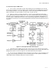
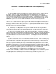
b. Figure U-3 shows a heterodyne transmitter. It consists of an IF amplifier and a microwave
source, both of which feed an up converter mixer. The source is similar to that used in the remodulating
transmitter except it need not be modulated. The mixer heterodynes the 70 MHz IF input signal up to a
microwave signal +/-70 MHz different from the source frequency depending upon the sideband selected.
The sideband select filter passes the desired sideband while rejecting the undesired sideband and source
frequency.
Figure U-3. Heterodyne Transmitter Block Diagram
c. A microwave power amplifier is then used to restore the level of the signal to its desired value.
Impact Avalanche and Transit Time (IMPATT) diode reflection amplifiers have been the norm and are still
being produced, but the current move appears to be towards GaAs FET power amplifiers.
d. At a repeater, the 70 MHz IF input to the transmitter comes from the receiver IF output at a level
of +5 dBm. If the heterodyne transmitter is used at a terminal station, the video signal first modulates a
70 MHz FM transmitter (modulator) which then feeds the transmitter.