
Service manual


STP 11-25R13-SM-TG
U - 6
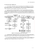
o. Other Noise Performance Factors.
(1) The 70 MHz IF preamplifier is often mechanically integrated with the mixer to achieve best
overall noise figure of the receiver. The preamplifier typically has 25-dB gain and is 50 to 60 MHz wide.
(2) Optimum receiver noise performance is achieved when the minimum necessary bandwidth is
used. This is typically 30 MHz to the 3-dB points for TV transmission. However in many metropolitan
areas, frequency congestion is pushing usage to 20 MHz wide IF bandwidths. Since the basic IF
amplifier circuits are 50 to 60 MHz or more wide, a lumped constant filter located between the
preamplifier and the main IF is employed to reduce the noise bandwidth of the receiver to 30 MHz. The
characteristics of this filter must be carefully controlled for good phase and amplitude linearity.
p. Providing IF Gain.
(1) The main IF amp follows the filter and provides typically 65 dB of gain. In both pre and main
IFs, discrete common-base transistor design had previously been used. This effectively isolates the
transistor characteristics from the overall amplifier performance characteristics that are determined
primarily by the interstage coupling circuits. With this design approach, the receiver characteristics are
essentially independent of the transistor characteristics that may vary widely with temperature.
(2) However, current approach is to use special purpose ICs or RF modules to provide IF gain.
The output level of the IF is typically +5 dBm. The input microwave level to a typical receiver may vary
from -25 to -80 dBm during fading conditions. Since a +5 dBm output is required, the gain needed varies
from 30 dB to 85 dB. In order to keep the output constant, 60 dB of AGC is typically used to regulate the
90 dB gain in the two IF amplifiers between 40 and 90 dB. Since portable and mobile equipment
operates over wide ranges of distance, it is important that receivers have at least 60 dB of AGC.
q. Other Parts of the FM Receiver.
(1) The limiters are an essential part of a FM receiver because they effectively eliminate the effects
of AM variations on threshold performance. Typically 20 dB of limiting is used.
(2) The discriminator demodulates the FM signal back to video. In a wideband TV system, it is
important to keep the discriminator linear over a wide bandwidth, typically 5 MHz or more about the
center 70 MHz IF frequency. Nonlinearity will produce distortion and noise on the signal by increasing
intermodulation between various components of the TV signal.
(3) The video amplifier brings the discriminator output signal back up to one volt. It also includes a
de-emphasis network that is exactly matched to the transmitter preemphasis network so that an overall
flat frequency response is achieved through the system. The video amplifier includes a LPF to reduce
the level of the audio subcarriers at the video output. While the degree of audio subcarrier rejection is not
extremely important in TV microwave signals, it is typically 30 to 40 dB below peak video levels. A high
degree of feedback is used in the video amplifier to achieve maximum stability.
(4) The preselect filter at the receiver input is used to improve selectively, prevent local oscillator
radiation, and suppress image frequencies. It typically consists of five or more filter selections designed
and tuned to cover several channels in switch-tunable systems or a single channel in fixed signals. The
bandpass characteristics must be closely controlled to avoid phase nonlinearities in the system.
(5) The same comments made for the transmitter regarding portable and vehicular applications
apply to the receiver.