
Service manual


STP 11-25R13-SM-TG
U - 5
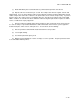
Figure U-2. Receiver Block Diagram
(2) Mixers are usually balanced mixers and often double balanced. If no low-noise amplifier (LNA)
is used, the mixer determines the noise figure of the receiver that is in turn largely dependent on the
diodes used. The mixer function is to produce an IF frequency by generating the difference between the
local oscillator frequency and the received carrier frequency.
n. Using a LNA.
(1) For superior noise performance and fade margin, a LNA may be added to the receiver design.
Using a LNA, receiver noise figures of 1.5 dB at 2 GHz rising to 3 dB at 13 GHz are achievable. Modem
LNA designs are based on GaAs (Gallium Arsenide) field-effect transistor (FET). Previously, tunnel diode
designs were used at 7 and 13 GHz while bipolar transistors were used at 2 GHz. The gain of these
LNAs is typically 15 to 20 dB.
(2) LNAs are also available separately for use outside the receiver. In this case, they are often
mounted near the antenna and are provided with a weatherproof housing. In this case, the loss of the
transmission line is eliminated and the system improvement is further increased. Another potential
application of the LNA is between two back-to-back dishes operating as an active repeater. FCC action
on this configuration is imminent. The LNA is a useful tool to the microwave design engineer, and its use
in the system should not be overlooked.
(3) The local oscillator carrier is usually crystal-controlled to 0.005 percent or better of the output
frequency. This eliminates the need for receiver AFC.
(4) Fundamental oscillators are usually used, but lower frequency oscillators followed by multipliers
are occasionally used as well. For frequency-agile equipment, up to 10 switch selectable crystal
references may be used or a suitable synthesizer employed.