
Service manual


STP 11-25R13-SM-TG
S - 30
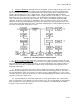
(3) In the mixer section of the colorplexer (refer to Figure S-24), the outputs of the Y, I, Q, and burst
keyer sections are added together to form the composite color signal.
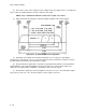
NOTE: Sync is added in the luminance channel for a single color camera.
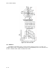
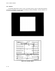
(4) Figure S-29 shows the bandpass now formed with the addition of the I and Q signals.
Figure S-29. TV Channel with Color Components
(5) Knowledge of the NTSC color transmission principles is necessary before pursuing the
operation of the color camera. The use of a specific frequency for the chrominance subcarrier results in
an interleaving of the luminance and chrominance signals.
(6) This interleaving of signals makes it possible to transmit both the luminance and chrominance
signals within the same channel bandwidth used for the transmission of a monochrome signal. The
composite color signal contains a luminance, chrominance, burst, and sync signal.
(7) The luminance signal represents the brightness elements of a scene. The chrominance signal
represents the colors of a scene. The burst signal is used as a phase reference.