
Service manual


STP 11-25R13-SM-TG
S - 29
g. Two-Phase Modulation
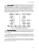
(Generation of the Color Signal). Refer to Figure S-28, where the I and
Q output of the filter section feeds two doubly balanced modulators where two-phase modulation takes
place. Two-phase modulation is a technique by which the I and Q signals can be combined into a two-
variable signal for transmission over a single channel. This is accomplished by adding sidebands
obtained through modulation of two 3.58 MHz carriers separated in phase by 90 degrees. The resultant
waveform is the vector sum of the components. The doubly balanced modulators suppress the two
carriers, which are derived from the same oscillator. Thus, only the two amplitude-modulated (AM)
sidebands, 90 degrees out of phase, are transmitted. At the receiving end of the system, the I and Q
signals are recovered by heterodyning the two-phase wave against two locally generated carriers of the
same frequency (but with a 90-degree phase separation) and applying the resultant signals through low-
pass filters to other matrix circuits in the receiver.
Figure S-28. Two-Phase Modulation Block Diagram
h. The Color Synchronizing Signal
. Since the subcarrier is suppressed at the encoder, the local
3.579545 MHz (3.58 MHz) oscillator at the receiver must be accurately synchronized in frequency and in
phase with the master oscillator at the transmitter. In order to maintain these two oscillators in phase, a
short burst of the transmitter 3.579545 MHz oscillator voltage is transmitted at the beginning of each
horizontal scanning line.
(1) The burst is generated at the color frequency standard generator by a gating circuit which is
turned on by burst keying pulses derived from a device known as the burst flag generator. This device is
also locked in with the station sync generator. The burst consists of approximately 9 to 11 cycles of the
3.58 MHz signal and is placed on the back porch of the horizontal blanking pedestal next to the horizontal
sync pulse (refer back to Figure S-15).
(2) FCC standard phase relationships between the I and Q signals and the color synchronizing
burst are shown in the vector diagram (refer back to Figure S-23). The I and Q signals are transmitted in
phase quadrature; the color burst (referred to as reference subcarrier) is transmitted with an arbitrary
57 degrees phase lead over the I signal.