
Service manual


STP 11-25R13-SM-TG
S - 27
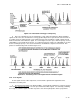
c. The Y Signal
is formed by applying the red, green, and blue pickup tube outputs to the base of
an amplifier (see Figure S-25). Thus the three signals are in phase with each other, input and output. A
resistor network (cross-connected voltage divider) determines that the amplitude of the Y amplifier output
will consist of 30 percent red, 59 percent green, and 11 percent blue. This Y signal corresponds to the
variations of brightness in the scene being televised. This is the signal received by a black and white TV
receiver, and is the brightness component in a color receiver.
Figure S-25. Y Matrix
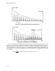
d. The I Signal
is formed by applying the red signal to the base and by applying the green and
blue signals to the emitter of the I amplifier (see Figure S-26). This circuitry determines that the output of
the red signal will be 180 degrees out of phase with the other two, thus the designation 60 percent red, 28
percent green, and 32 percent blue. The polarity signs only indicate phase relationships. The resistor
network determines the amplitude of the signals.
Figure S-26. I Matrix