
Service manual


STP 11-25R13-SM-TG
R - 2
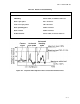
expected at contacts 2 and 4, with a zero volt reading at contact 5. Improper readings would indicate a
malfunction.
R-3. Ohmmeter Checks.
a. Ohmmeter checks are performed with the power removed from the entire circuit and with the
relay isolated from the rest of the circuit. A resistance check of the coil should usually read from 100 to
400 ohms on most relays.
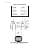
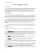
b. A resistance check of the deenergizing contacts (2 and 4 or 6 and 8) in Figure R-1 should
indicate continuity with the relay off and disconnected. A resistance check of the energized contacts (2
and 5 or 6 and 1 in Figure R-1) should indicate discontinuity (infinite resistance).
c. Resistance checks of the switching contacts can safely be done with power applied to the coil in
some situations.
d. If a relay is malfunctioning, it is usually replaced because most relays are sealed units that
cannot be repaired. Be careful when replacing relays to avoid incorrect or shorted connections that could
cause damage to the equipment being repaired.